Clean-In-Place (CIP)
CIP is a method of cleaning the interior surfaces of pipes, vessels, filters and other processing equipment without disassembly. The benefit is that the cleaning is faster, less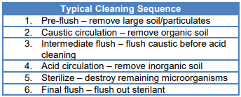 labor intensive and more repeatable while also posing less risk to chemical exposure of workers. The cleaning cycle is comprised of different stages with water and/or cleaning solutions that require a certain time, temperature, flow, velocity and detergent concentration to achieve the necessary results.
The challenge is that to remove soils, CIP solutions must reach the surface and soil to have an effect.
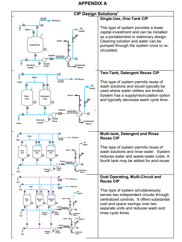
CIP systems can be designed as a single-use CIP or re-use CIP. While single-use CIP has a lower initial investment, long-term cost is higher as chemicals are dumped after each cycle. Cycle time is also typically longer with single-use system as time is needed to do water fills and heat the water. Re-use CIP systems recover ~80% of the chemical and water volume. Utility costs can also be realized by saving heated solutions. Several design options are shown in Appendix A. Flow of liquid is responsible for carrying both hot water and cleaning solution to the soil on a surface and also for providing the physical mechanism of lifting and carrying the soil away. Studying the flow conditions during CIP can help insure the system is meeting cleaning requirements. Depending on soil load and the process layout, CIP design is typically one of
the following:
Deliver highly turbulent, high flow-rate solutions (i.e. piping and some equipment)
Deliver solution as a low-energy spray to fully wet the surface (lightly soiled vessels with static sprayball)
Deliver solution through a high-energy impinging spray (highly soiled or large diameter vessels with dynamic spray)
When evaluating a new CIP system (or an upgrade to your existing system), consider a few basic design requirements:
The flow rate to clean vertical tanks with fixed spray balls is 2.5-3 gpm x tank circumference
The flow rate to clean horizontal tanks with fixed spray balls is 0.25 gpm x surface area (sq.ft.)
Add additional flow devices for agitators, baffles, etc.
The effective spray distance is ~8 feet radius.
Increase spray ball flow rate to clean outlet piping at 5 ft/second if required.
Minimum CIP supply pressure required is 15 psi.
Clean-Out-Of-Place (COP)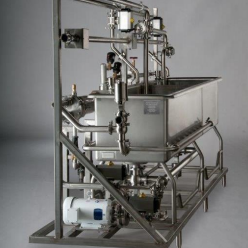 COP systems are used to clean equipment parts and components. They provide consistent, repeatable cleaning with reduced chemical and water usage, less labor and faster cleaning than hand washing. COP is typically used for pump rotors, impellers, cases, hoses, tubing, fittings, gaskets and any other handling equipment. COP washers can be designed as portable/skid or stationary systems with single or multiple compartments. Standard models are typically built with a 304L stainless steel construction with jet manifolds and a centrifugal pump to pump the water and cleaning solution through the system. Designs can be further upgraded to 316L stainless and can include a heat exchanger and PLC controls for semi-automation of sensors and feed systems.
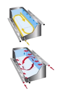
When sizing and specifying a COP system, one should consider:
Industy/Application – finish level, control and recording needed
Product soil type and condition – baked on, loose, wet, etc
Largest component(s) that must be washed – loading and spacing
Type and configuration of components – tubing, machine parts, etc
Batch size – quantity of items and turnaround time available
Utilities available
Location in your facility – space limitations, portable or fixed
One final consideration with COP systems are the jet manifold options. Spray jets can be mounted as side jets or end jets. With end jets, a pump forces the cleaning solution from one end to create a counter-current lengthwise circulation. This type of circulation would be recommended for tubing and hoses to clean the inner diameter. Side jets are mounted around the outside of the tank; pointing up and down to create a rolling turbulence. For deeper tanks (>24”), a second manifold is added to each side to create a quad-jet manifold. Combination washers can be designed to include both side and end jets. In this system, butterfly valves allow the operator to switch between the two circulation systems.