Pump Problem Solving – Cavitation
For all pump application problems, cavitation is the most common issue we encounter. It occurs with all types of pumps – centrifugal, rotary or reciprocating. Cavitation is the formation of vapor cavities in a liquid – i.e. small liquid-free zones (“bubbles” or “voids”) – that are the consequence of forces acting upon the liquid. It usually occurs when a liquid is subjected to rapid changes of pressure that cause the formation of bubbles where the pressure is relatively low. These bubbles are carried along by the fluid and implode instantly when they get into areas of higher pressure.
According to the Bernoulli Equation, this may happen when the fluid accelerates in a control valve or around a pump impeller. Cavitation can result in a loss of pump efficiency/flow, noise and possible damage to the pump and/or system. The vaporization itself does not cause the damage – the damage happens when the vapor almost immediately collapses when the velocity is decreased and pressure increased. When a pump cavitates, the vapor bubbles move toward the impeller where they collapse.
This causes a physical shock which creates small pits on the edge of the impeller. Each individual pit is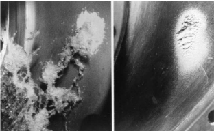 microscopic in size, but the cumulative effect of millions of pits over a period of time can destroy a pump impeller. Cavitation can also cause excessive pump vibration which damages bearings, wearing rings and seals. Noise is typically the indication that a pump is cavitating. Other indications that can be seen include fluctuating discharge pressure, flow rate and pump motor current. Excessive pump speed and/or adverse suction conditions will probably be the cause.
Suggestions for avoiding or minimizing cavitation:
Use the 1.5 multiplier for suction tubing (a 2” pump should have a 3” suction tubing and reduce to 2” at the pump)
– Note – this could cause excessive pump sizing for CIP flow rate. This is only recommended when cavitation is a concern.
Use the 7 to 10 diameter rule for straight tubing. No elbows directly into the pump.
Fluid viscosity kills – stay under 5 feet per second.
Maintain a static head as high as possible.
Reduce fluid temperature, although caution is needed as this may have an effect of increasing fluid viscosity, thereby increasing pressure drop. If cavitation is a concern, it is strongly recommended that you contact an engineer to review your process.
Slip
Slip occurs in PD pumps when fluids passes from the discharge side back to the inlet side of the pump through the pump clearances. It is the difference between the theoretical displacement and the actual displacement. Slip is caused by three factors: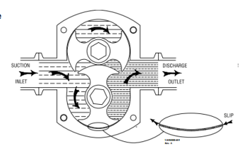
Viscosity – Slip will decrease as fluid viscosity increases; the
reduction eventually reaches a point called “zero slip”.
Pressure – Slip will increase with pressure increases
Clearance – Increased clearances will result in greater slip.
The size and shape of the rotors will be a factor.