Skip to content

The Pump Overview Part 1 

A pump is simply defined as a device that raises, transfers, delivers, or compresses fluids or that attenuates gases especially by suction or pressure or both. Pressure, friction and flow are three important characteristics of a pump system. Pressure is the driving force responsible for the movement of the fluid. Friction is the force that slows down fluid particles. Flow rate is the amount of volume that is displaced per unit time.

Pumps are typically classified by the way they move fluids. For the sanitary industry, we will only focus on positive displacement pumps and centrifugal (or rotodynamic) pumps. Positive displacement pumps include single and double rotary lobe pumps and diaphragm pumps. The table below outlines a few of the basic differences between these pumps.

Positive Displacement Pump

A positive displacement (PD) pump makes a fluid move by trapping a fixed amount and forcing (displacing) that trapped volume into the discharge pipe.

Some positive displacement pumps use an expanding cavity on the suction side and a decreasing cavity on the discharge side. Liquid flows into the pump as the cavity on the suction side expands and the liquid flows out of the discharge as the cavity collapses. The volume is constant through each cycle of operation.

Positive displacement pumps, unlike centrifugal or roto-dynamic pumps, theoretically can produce the same flow at a given speed (RPM) no matter what the discharge pressure. Thus, positive displacement pumps are constant flow machines. However, a slight increase in internal leakage as the pressure increases prevents a truly constant flow rate.

For each revolution of the pump, a fixed volume of liquid is moved regardless of the resistance against which the pump is pushing. Therefore, a positive displacement pump must not operate against a closed valve on the discharge side of the pump, because it has no shutoff head like centrifugal pumps. A PD pump operating against a closed discharge valve continues to produce flow and the pressure in the discharge line increases until the line bursts, the pump is severely damaged, or both.

A relief or safety valve on the discharge side of the positive displacement pump is therefore necessary. The relief valve can be internal or external. The pump manufacturer normally has the option to supply internal relief or safety valves. The internal valve is usually only used as a safety precaution. An external relief valve in the discharge line, with a return line back to the suction line or supply tank provides increased safety. PD pumps are designed with very small clearances between the rotating lobes and the stationary parts to minimize leakage (slippage) from the discharge side back to the suction side. They are designed to operate at relatively slow speeds to maintain these clearances; operation at higher speeds causes erosion and excessive wear, which result in increased clearances with a subsequent decrease in pumping capacity.

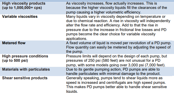
When would you choose a PD pump? Typically, PD pumps are selected for the following scenarios:

Diaphragm Pumps

A diaphragm pump (also known as a Membrane pump, Air Operated Double Diaphragm Pump (AODD) or Pneumatic Diaphragm Pump) is a positive displacement pump that uses a combination of the reciprocating action of a rubber, thermoplastic or Teflon® diaphragm and suitable valves either side of the diaphragm (check valve, butterfly valves, flap valves, or any other form of shut-off valves) to pump a fluid. This implies that the pump will deliver a specific amount of flow per stroke, revolution or cycle.

Air operated double diaphragm pumps have the following components:
 Air chambers: The pump has two chambers, one on the left side and the other on the right side of it. These chambers let the compressed air flow in and out of it.
 Air valve: The compressed air is directed to air chambers with the help of air valves. These have a valve cup and a valve plate. Air valves make sure that the compressed air enters the air chambers and leave from it through the exhaust port

 Check valve: There are four fluid check valves in a double
diaphragm pumps. Two of them are inlet check valves while the other two are outlet check valves. The flow of liquid in the fluid housing and manifolds is controlled by these check valves.
 Fluid housing: Each pump has fluid housing, one at each side of the pump. As the name implies, fluid housing is that part which holds the fluid and makes it flow through the pumping mechanism.
 Inlet manifold: Fluid enters the pumping container via the inlet manifold and flows evenly to the left and right fluid housing. This mechanism makes the distribution of fluid equal so that both fluid housings remain in operation.
 Outlet or Discharge manifold: When the fluid is coming out of the container, it passes through a couple of components. First, the fluid passes through one of the exit check valves and then this check valve directs the fluid to the outlet manifold to finally exit the container altogether.
 Diaphragms: The air operated double diaphragm pump obviously has two diaphragms in it. The diaphragm is actually a kind of a separation sheet in between the air chambers and fluid housings. The diaphragms are good enough to adjust
themselves according to the rise or fall of the air pressure, as the condition may be. Besides, the two diaphragms are allied with a shaft.
 Muffler: The objective of muffler is to control noise of the exhaust air. There are multiple mufflers available that offer several levels of noise reduction to ensure effective and efficient pumping operation.
 Exhaust port: The exhaust port is the final exit point in the pump.

How Does An Air Operated (Double) Diaphragm Pump Work?

Using compressed air as the resource to operate, double diaphragm pumps are meant for low pressure activities mainly. A vacuum is formed inside the pump casing each time the diaphragm is raised. This allows the inlet valve to open and seals the discharge valve thus allowing water and air to enter the pump. Whenever the diaphragm is lowered the resulting pressure seals the inlet and opens the outlet valve purging the pump housing of water and air.

In summary, the process is given below:
1. Chambers are filled with fluid and then emptied through an ongoing process. This is done through inlet and outlet manifolds.

2. The shaft joining the left and right diaphragms in each chamber enables them to move to and fro continuously.

3. Compressed air is directed to one of the diaphragms.

4. Eventually as the suction stoke occurs, the lower ball valve opens and the top one closes. Simultaneously, fluid enters the chamber through the inlet manifold.

5. When air enters the other diaphragm, the top ball valve opens and the lower one is closed. This allows the fluid to exit through the outlet manifold.

6. The same process repeats with the other chamber and it goes in cycles between the two chambers

When would you choose a diaphragm pump? 

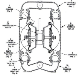
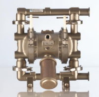
The compressed air design gives diaphragm pumps the ability to run without electric power. Otherwise, diaphragm pumps offer many of the same benefits of a traditional lobe-style PD pump. They have a low initial cost, are easy to maintain and simple to install. They can handle shear-sensitive products and have the ability to process delicate materials without damage to the product. Diaphragm pumps are self-priming with excellent flow rates. Common applications include ingredient unloading (tote or drum unloaders), filler feeding and batch metering processes.

Diaphragm pumps:
• have good suction lift characteristics
• are able to handle a wide range of pressures and can deliver flow rates up to 300 gpm, dependent on the effective working diameter of the diaphragm and its stroke length.
• have good dry running characteristics.
• can be up to 97% efficient.
• have good self-priming capabilities.
• can handle highly viscous liquids (up to 1,000,000+ cps). A viscosity correction chart can be used as a tool to
help prevent under-sizing AODD pumps.

If you want more information, contact us by phone or email.