Electric vs Pneumatic Actuators

Electric vs Pneumatic Actuators 

While electrical and pneumatic actuators have several unique benefits and are preferred in different applications, using
the wrong one for your application can have serious consequences. It’s important to understand the principles and
differences between pneumatic and electric actuators before comparatively analyzing their features to help you choose
the right one for your application.

Valve actuators are automation devices that are used to remotely control valves without human intervention. These devices generate motion to control valves based on signals received. Actuators are mounted on the valves to be controlled, replacing manual levers. The mounting features that connect a valve to an actuator vary in
different actuator models. Valve actuators are broadly classified based on how they generate the torque – or force – required to open a valve. Based on this classification, the two most prevalent types of actuators are electric and pneumatic actuators. Electric valve actuators utilize electricity to produce the required motion, while their pneumatic counterparts utilize compressed air systems.

Electric actuators
Electric actuators convert electrical energy into the force that opens or closes the valve. These devices may run on AC or DC power. Electric valve actuators may feature an electric motor that produces the rotary motion that turns the valve. This type of actuator is used for quarter-turn valves, which require a 90° turn to open or close, and are known as quarter turn actuators. Examples of quarter-turn actuators are ball and butterfly valve actuators. Another widely used type of electric actuator in piping and fluid control systems is the solenoid actuator. These devices are typically available integrated with the valves, forming a single unit.

On the other hand, in double-acting actuators, the air is
supplied to both sides of the piston. The difference in pressure
between the two sides keeps the valve in the desired position.
Pneumatic actuators typically produce linear motion. However,
in actuators such as butterfly valve actuators (which are
required to generate rotary motion), motion conversion
mechanisms – such as rack and pinion, and scotch yoke
mechanisms – are used.
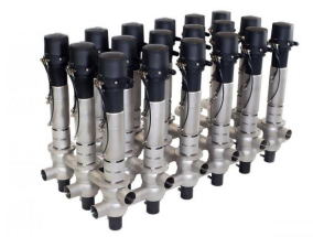
Pneumatic actuators
Pneumatic actuator utilizes pneumatics – controlled compressed air systems – to produce the force required to operate a valve. These actuators may feature a piston, or diaphragm, that is controlled via compressed air. Pneumatic actuators may be single-acting or double-acting. Single-acting actuators, more commonly known as spring return actuators, feature a loaded spring on one side of the piston that keeps the valve in its natural position. To open or close the valve, pressurized air is supplied on the other side of the piston, and the air pressure overcomes the force of the spring.

Seven considerations to choose between an electric and a pneumatic actuator

Both electric and pneumatic valve actuators have specific advantages in different applications. To choose the right one for your application, certain factors and characteristics of these actuators must be analyzed. Some of these factors and characteristics are explored below.

1. Precision
Precision is considered for valves that need to operate in partially open or closed positions to allow an exact amount of media to flow through. Both electric and pneumatic actuators provide precise control. However, when relying on
pneumatic actuation, the inclusion of an electro-pneumatic positioner may be required as an accessory on a pneumatically operated device such as a control valve to achieve the high precision control necessary in applications.
2. Force range
Pneumatic actuators provide a significantly higher force/torque per unit side than their electric counterparts. For applications that involve a large valve or a valve with high operating pressure, pneumatic actuators are the better option.
3. Speed
Speed of actuation is a crucial consideration in specific applications. Like with precision, both electric and pneumatic actuators can be fast. However, a pneumatic actuator reacts faster and has high duty cycles. Furthermore, the operating
speeds of pneumatic actuators are adjustable.
4. Lifespan
Pneumatic actuators have fewer components. Therefore, they are easier to maintain and have a longer lifespan than electrical actuators, which have several parts that may require regular maintenance. However, while the actuator unit
may not require maintenance, other components such as the air compressor and the FRL (Filter, Regulator, and lubricator) may require more frequent maintenance
5. Cost
The design of pneumatic valve actuators is more straightforward than that of their electric counterparts, and so these actuators cost less than electric counterparts. However, when the cost of the accompanying pneumatic system is
considered, the overall cost of a pneumatic actuation system increases. This cost can be significantly reduced by setting up numerous actuators with the same pressurized air supply system.

6. Fail safe
In applications where a failure in the actuator can have severe consequences, the actuator needs to have a fail-safe mechanism. A fail-safe is easier and cheaper to install in pneumatic actuators. Spring return pneumatic valve actuators feature a natural fail-safe mechanism, as the force of the spring will automatically return the valve to its natural position in the case of a failure.

7. Hazardous conditions
Electric actuators often feature delicate components that may not function correctly in hazardous conditions. Furthermore, these actuators require numerous certifications to be deemed suitable in certain environments. Electric actuators need a high level of protection against high temperatures and pressures, dust, and moisture. On the other hand, pneumatic actuators are quite rugged and can withstand higher pressures and temperatures than their electric counterparts.

If you want more information, contact us by phone or email. 

Sanitary Check Valves Overview

An Overview of Sanitary Check Valves  

A check valve – also called a one-way valve or non-return valve – allows for fluids to flow in one direction only, hence the “check”. The valves have two ports – one for entry and another for exit. Check valves are used in a wide range of
applications, both sanitary and industrial, including condensate lines, pump discharge lines, steam lines and more. The purpose of a check valve is simple – they prevent back flow in your process. As a manual valve, they work automatically and are typically not controlled by any external control. In sanitary processing, check valves are typically 316L stainless and are CIP’able when installed properly. In other applications, check valves may be made of plastic or some other composite material. The two basic types of sanitary check valves are the disk type and the ball type.

Ball Check Valves 
Ball check valves have a Y body configuration. The closing portion of the valve is a ball, either spring-loaded or gravity operated. During product flow, the ball is pushed up into the Y branch of the valve out of the product stream; allowing full flow through the valve. The combination of gravity and back pressure pushes the ball back against the valve seat in the main run of the valve when flow is stopped. Ball valves can be installed vertically or horizontally. In a vertical installation, product must flow from bottom to top in order for
gravity to seat the ball. In a horizontal installation, the curved portion of the valve should be upright and perpendicular to the pipe to ensure that it is free-draining and that the ball seats properly. 

When selecting a ball check valve, make sure to pick the correct elastomer ball for your application. Balls are normally available in Buna, Viton®, and EPDM. Choose the material that is compatible with your product. 

Disk Check Valves
Disk check valves have a straight through body with a valve seat machined into the valve. An insert holds a metal disc that is normally spring loaded to push against the valve seat. During product flow, the disk is pushed away from the seat. When the flow stops, a spring returns the disk and holds it closed against the seat. Back flow pressure also pushes the disk into the closed position. These valves are available with either a straight metal seat or a metal seat with an O-ring seal. The O ring seal option is used to ensure proper sealing as metal seats alone do not always create a perfect seal. They can be used in either horizontal or vertical applications, however if free-draining is required, the horizontal mount is recommended.

Disk check valves typically cost less than other standard valves and are smaller and lighter. However, they are not recommended for applications where there is heavy, pulsating flow.

Thick, sticky products can also be problematic with ball check valves. In these cases, the ball can sometime stick in the Y branch and not properly reseat itself when flow stops. You can PIG your line through a ball check valve. Ball check valves have virtually no pressure drop. Some ball valves have an optional air blow check. This feature is used to isolate upstream equipment so that lines can be evacuated of product or CIP solution using air. These valves may also be used when passivating process lines.

Disk check valves are available with a wide range of springs to provide greater precision on the pressure needed to “crack” or open the valve during operation. Disk check valves will have a higher pressure drop since the disk is in the flow path.

If you want more information, contact us by phone or email. 

Maintaining Hygienic Valves

Maintaining Hygienic Diaphragm Valves 

A process-specific preventative maintenance program improves productivity and reliability.

The biopharmaceutical industry relies on hygienic diaphragm valves for its demanding process applications due to a
unique need for cleaning and draining and for pressure and temperature capabilities. Over the past 40 years, the basic
design of such valves has remained the same: body, diaphragm, topworks, and four fasteners (see Figure 1). Properly
installing and maintaining these valves requires experienced personnel and stringent maintenance practices to assure
consistent and reliable valve performance.

Preventative Maintenance Benefits
Facilities can cut costs and decrease downtime through preventative maintenance, which involves a schedule and process for maintaining equipment; preventative maintenance is particularly important when it comes to valves. Although it can take hundreds of hours a year to
properly maintain hygienic diaphragm valves, resulting in thousands of dollars of maintenance cost and lost hours of production, the primary function of a maintenance program is maximized production up-time, reduced planned and unplanned man-hours of labor, and early detection of diaphragm failure. Many plants fail to have a maintenance schedule for their hygienic diaphragm valves and may even wait until a piece of equipment fails before performing any maintenance at all– resulting in a costly and lengthy plant shutdown. Failure of the diaphragm, which will occur if it is not replaced on a
routine basis, will most likely contaminate the process somewhere along the process lines. In many cases, the three major types of failures include valve leakage (fluid leaks between diaphragm and valve body to atmosphere), complete diaphragm rupture (diaphragm tears allowing process fluids to escape through the valve bonnet), and diaphragm tears (diaphragm tears allowing process fluids to escape through the valve bonnet). The result of these failures can be loss of product. In addition to the product that leaks out, a leak can put the entire batch at risk because of possible contamination entering the system. A diaphragm rupture can introduce contamination from the non-sterilized internals of the valve topworks, allowing the product to come into contact with greases and other contaminating liquids. Diaphragm tears can cause contamination from fluids that get entrapped in the diaphragm tears.

How to maintain hygienic diaphragm valves 

Hygienic valves act as both the static seal (shell seal) and a dynamic seal (weir shutoff). They are often exposed to harsh chemicals, high temperatures, and high pressures, resulting in high amounts of wear and tear and an increased need for routine maintenance. Proper valve maintenance requires several steps by the maintenance team to ensure that the valve will function to its full potential.


Diaphragm tears can be especially insidious; because the pressure boundary of the diaphragm is not breached, the in-line instrumentation does not detect a system problem. Many times, all of the process fluids produced from the time of
detection of the problem may be recalled or put on hold for testing. Valve leakage can also result in lost production time and an additional need for maintenance and time to clean up the equipment and repair the leaking valve. Additionally, valve leakage can cause potential safety risk, including employee exposure to dangerous process fluids, steam leaks, clean-in-place fluids, and dangerous organisms. Preventative maintenance can help maintain these seals and decrease the risk of leakage. Ultimately, detecting failures before they occur can result in improved sterility and minimized risk of contamination, and therefore, reduced maintenance hours and commissioning. Additionally, going through the process of preventative maintenance reduces the need for managers to unnecessarily replace valves or react to potential problems that can occur, resulting in greater efficiency, reliability, and ease of use. The keys to proper valve maintenance are knowing the steps involved in maintaining valves and implementing a preventative maintenance plan that works for a particular facility and application.

Valve assembly/installation. One of the most important parts of maintenance is proper assembly during the diaphragm change-out process. If the valve is not assembled properly, it can leave room for batch contamination, poor valve performance, and short lifecycle. Proper diaphragm installation per manufacturer’s instructions is essential. If installed improperly, excessive force during operation can result in diaphragm damage. Fluids can then pass through the closed valve or, in the worst case, cause catastrophic failure that results in process fluid contamination and leaks. Torqueing and retorqueing are also important steps in the assembly process that can often lead to seal failure, by either making the seal too tight or too loose for proper performance.

Replacing the diaphragm. Another aspect of valve maintenance is knowing when a replacement diaphragm is needed. To make sure valves do not fail, some companies change out their diaphragms on a regular basis (e.g., every six months), regardless of whether or not it is needed. Facilities that use diaphragms with a shorter life expectancy, such as rubber-type diaphragms, may be more likely to perform require more regular changes. However, consistently replacing diaphragms with no signs of failure can cost plants unnecessary expenses and time. Knowing the signs of valve failure is also essential to maintaining a facility’s valves. Physical signs that a valve or diaphragm needs to be replaced are excessive wear, corrosion, or fluid leakage.

Improved valve designs
In recent years, the design of the hygienic diaphragm valve has been optimized to increase productivity, ultimately advancing maintenance practices in biopharmaceutical facilities. New valve technology, for example, can reduce average diaphragm replacement time from 23 minutes to three minutes and total maintenance time from hundreds of man hours to just a few hours, hence reducing maintenance cost by more than 90% (2). Preventative maintenance practices and more innovative technology, such as valves that do not require tools or re-torqueing, are preventing the potential of human error and making processes safer and more efficient. Improved designs can help meet the biopharmaceutical industry’s growing demand for increased productivity, extended maintenance intervals, and reduced operating costs, in conjunction with an effective preventative maintenance program.

Factors to consider
Because of the wide range of applications and conditions within the pharmaceutical processing industry, preventative maintenance programs should be built up over time and should be specific to the application. Programs can vary widely from one plant to another. There are many factors to consider when facilitating a preventative maintenance program. The biopharmaceutical industry is fairly unique in that valves are used in many different applications with different exposures to temperatures and harsh fluids. Different applications for valves can include steam-in-place (SIP) or high-temperature sterilization; cleaning in place (CIP) where caustics and acids act as detergents; cold processing where purification is usually below ambient conditions (2-8 °C typically); and purification processes, such as chromatography and filtration. Many of these processes run in sequence or through the same pipes, which means the valves are exposed to a wide range of application temperatures and conditions. Other factors that affect valve performance and maintenance include the amount of exposure time to liquids and steams, the type of diaphragm (one-piece vs. two piece diaphragm), and the thermal cycle (the swings between minimum and maximum temperature). Diaphragms and other soft parts, such as gaskets and O-rings, often face fluctuations between
steam sterilization and cold-processing temperatures in the biopharmaceutical industry. A typical valve undergoes hundreds of thermal cycles in its maintenance lifecycle, which can affect the valve seal and ultimately the product. As
thermal cycles increase, the valve diaphragm is continually being compressed and relaxed, resulting in thinning of the diaphragm. These dimensional changes create less seal contact and will eventually result in valve leakage to the
atmosphere. Although some leaks can be addressed with re-torqueing, most end-user procedures do not allow valves to be re-torqued after the process has been released to production.
Thermal cycle performance has been a significant topic for the biopharm industry for some time. The American Society of Mechanical Engineers Bioprocessing Equipment Committee, which drives many of the industry best practices, has developed a test procedure that will help the end user determine the potential performance of a given seal/diaphragm in these varying conditions. This “Appendix J” test (1) allows seal/diaphragm manufacturers to rate the performance of their
elastomers based on a standard test protocol. This testing is currently non-mandatory and is in its infancy of adoption by the end users in the industry. Eventually these Appendix J ratings will provide end users a consistent basis to assess
expected life expectancy with regards to thermal cycle performance. Many of the forward-thinking pharmaceutical companies are now partnering with valve manufacturers to assess maintenance frequencies. With proper application data, including temperature, pressure, process fluid data, and exposure times, valve manufacturers can help develop a maintenance program that aligns with the risk profile of the end user. In this way, the end user can save unnecessary maintenance costs and production down time, ultimately reducing their total cost of ownership of the process system.

If you want more information, contact us by phone or email.