A Vanilla Victory with the Rotosolver
In the world of food production, staying ahead of the curve is essential. For companies dedicated to creating the finest products, innovation isn’t just an option—it’s a necessity. For one flavoring company, staying in front of taste trends allows them to lead the
market in designing and producing flavoring emulsions, extracts and powders for beverages, baked goods, confections and dairy.
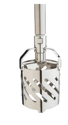
Making their French Vanilla flavoring was an all-day mixing marathon! The process for making the flavor mix had been the same for years. All the ingredients were added into a vat. The production team would turn on a mixer and let the mixer run overnight. They would come in the next morning and test to see if completely mixed. The flavor mix started as a hallowed orange initially but would turn to a French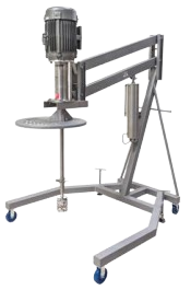 vanilla, creamy dark yellow color when well mixed. Our sales rep Jacklyn took the Admix Rotosolver® demo unit to the plant. The demo unit has a transparent tank which enabled the production team to watch the color change during the demonstration. Once the ingredients were added, the Rotosolver was turned on. After 7 minutes, the operators’ mouths were hanging open; the flavor mix had already changed color to the creamy, dark yellow they wanted.
 The following week, the customer placed an order for a Rotosolver unit on a portable stand and changed their mixing process. Efficiency isn’t just about speed—it’s also about costeffectiveness. The Rotosolver has significantly cut down on production costs. Reduced mixing times mean lower energy consumption, and the consistent results minimize waste due to off-spec batches. These savings are not only beneficial to the company’s bottom line but also align with their commitment to sustainable practices. Here’s to the perfect blend of tradition and innovation, and to many more delicious creations to come! We turned an 8-hour vanilla mix marathon into a 7-minute flavor sprint – that’s how We Make It Work Better!

 spins proportionally faster.