The Case of The Mismatched Pumps
Why Serial Number Integrity Matters in Pump Gear Case Repairs
Detective Newell had seen a lot of strange cases over the years, but this one arrived in a wooden crate—six pump gear cases, stacked like silent suspects, shipped in without explanation.
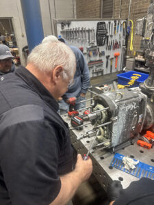 At first glance, something felt wrong. As the crate was opened, Detective Newell leaned in, scanning the evidence. No covers. No bodies. No rotors. Just gear cases—bare, incomplete, and unwilling to tell their story.
“Where’s the rest of the pump?” he muttered.
A call to the customer confirmed the first clue: they only wanted the gear cases evaluated. Detective Newell did his due diligence, examining each one carefully. The verdict was clear – repairs were possible, but not without the missing pieces. Covers, bodies, and rotors would all be required to close the case properly.
That’s when the plot thickened. Detective Newell was put in touch with the head of maintenance. The conversation started simply enough, but before long, a troubling truth emerged. The missing parts weren’t lost – they were still out there, circulating.
Being used.
Mixed.
Mismatched.
Each pump, Detective Newell explained, is born with a serial number – its identity. That number is stamped on the body and the cover, binding the components together as a matched set. The rotors inside are precision-machined, each one unique, each one designed to work with its original partners.
But these pumps? Their parts had been shuffled like cards in a bad poker game.
“That’s how pumps get destroyed,” Detective Newell said, laying out the facts. “Mismatched rotors don’t forgive. They bind. They lock up. And when they fail, they fail hard.”
The evidence was undeniable. Rebuilding the gear cases without restoring their original identities would be risky – no guarantees, no alibis. The pumps might run… or they might seize without warning.
Detective Newell closed his notebook. The case was solved, but the lesson lingered: Matched parts are essential to pump reliability.
With pumps, as in detective work, the smallest details matter. Ignore identity, mix the wrong parts, and failure is only a matter of time.
 Serial numbers exist for a reason—components are machined to tight tolerances and tested as a set. Ignoring that fact may keep a pump running temporarily, but it significantly increases the risk of failure.
Another mystery unraveled. Another reminder that precision is never optional. Proper repairs start with proper parts—and matching them correctly is the difference between long-term performance and costly breakdowns.

 and CIP solution. As seen in the picture, their old submersible mixer and motors were struggling in this harsh environment. Therefore, Plant associates were servicing and often replacing the motors every few months. Our M.G. Newell sales associate recommended a motor from Stainless Motors, Inc (SMI). SMI is a US-based manufacturer of stainless-steel wash-down motors, gear reducers and
  In our busy day to day operations, we sometimes lose sight of the time
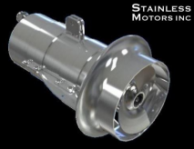
 mechanical force and converts the energy of a force into a digital or analog measurable output. The force applied to the load is proportional to the strength of the output. A load cell can use different methods to translate force into a weight measurement. This paper will cover designs according to the type of output signal generated – hydraulic, pneumatic and strain gauge. The most common load cell used in industrial weighing are strain gauge load cells.
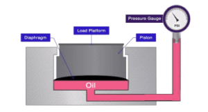
 heavy the
 Determining which load cell your

 were erratic and they were having to start and stop the process manually. The process was so troublesome that the brewer was intentionally overfilling kegs just to make sure they were not shorting their customers. The brewer was getting an ‘Error 900’ message, but after scouring their paperwork and the internet, no one could find that error message ANYWHERE! The kegging system was a European system with a European flow meter. The brewer was resigned to the fact that he was going to have to pay a technician to come from Europe to help identify and fix the flowmeter.
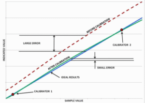 “Ideal Results”. However, without calibration, an actual product may produce test results different from the sample value, with a potentially large error. Calibrating the product can improve this situation significantly. During calibration, the product is “taught” using the known values of Calibrators 1 and 2 what result it should provide. The process eliminates the errors at these two points, in effect moving the “Before Calibration” curve closer to the Ideal Results line shown by the “After Calibration” curve. The error has been reduced to zero at the calibration points, and the residual error at any other point within the
 standard is within its calibration interval and the unique identifier is recorded on the applicable calibration data sheet when the instrument calibration is performed. Additionally, when test standards are calibrated, the calibration documentation must bereviewed for accuracy and to ensure it was performed using NIST traceable equipment. M.G. Newell offers a variety of calibration services that keep your operations consistent and cost effective. Contact your local account manager for rates and plan options.