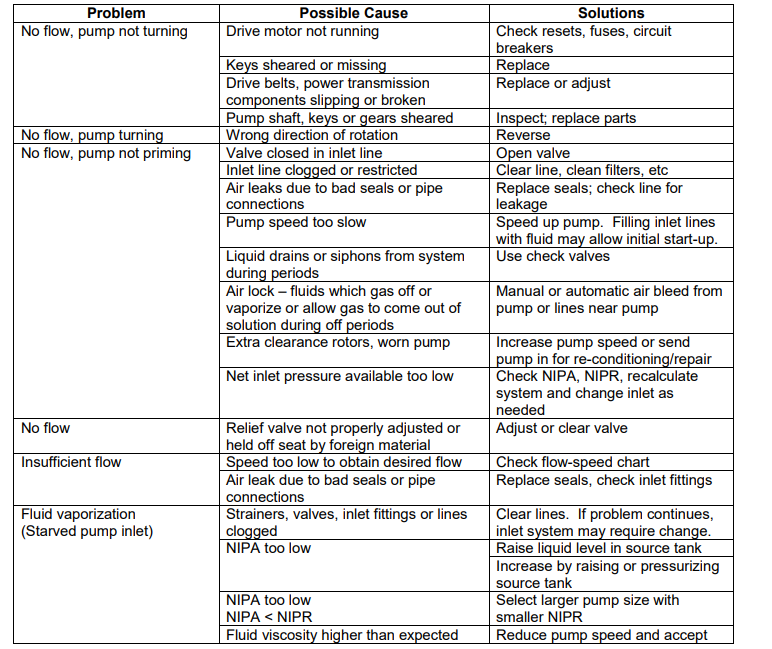
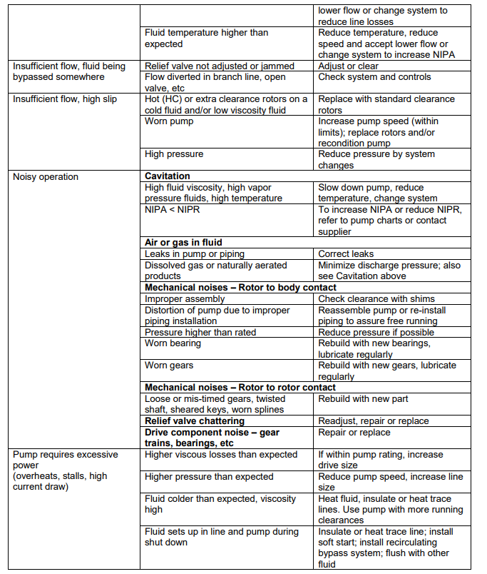
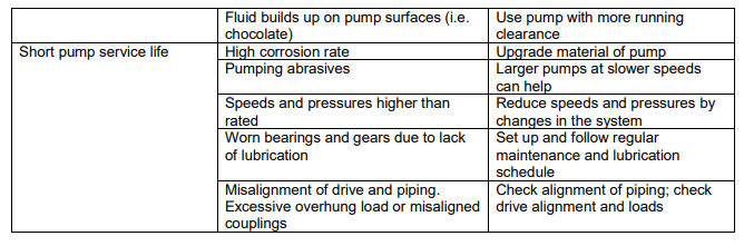
Trouble shooting a diaphragm pump

5 Minute Fix to Troubleshoot a Diaphragm Pump

Air-operated double diaphragm pumps (AODD) are preferred in transfer applications. Due to a simple design that makes
them easy to operate and cost effective to repair. But it is important to install and operate the pump correctly to achieve
top performance. Highlighted below are six quick and easy fixes to common problems you may encounter during
installation and operation.

Step 1. Check the Inlet Air Line Size and Pressure 

Installing too small of an air line is the most common mistake relating to an AODD pump. By using too small of an air
line, you are starving the pump of the fuel. It needs to operate at peak performance. Double
diaphragm pumps come in all shapes and sizes, based on the application and fluid requirements. Larger AODD pumps,
one inch and greater. Require more compressed air and larger air lines to operate at full capacity compared to smaller
pumps. You can find the appropriate air line size for your pump in the manufacturer’s installation and operation
manuals. As a general guideline for AODD inlet air line sizes. It is best practice to match the air line hose size to the air inlet port size on the air valve.
Inlet air pressure also plays a key role in getting the
most out of your pump. Diaphragm pumps operate
on a 1:1 ratio. Meaning the pressure of the inlet air
you feed the pump is directly related to the fluid
pressure at the outlet of the pump. For example, if
the target outlet pressure of a 1 inch, 50 gpm pump
is 100 psi. The inlet air pressure entering the air
valve of the pump must be greater than or equal to 100 psi.

System back pressure and fluid viscosity will impact
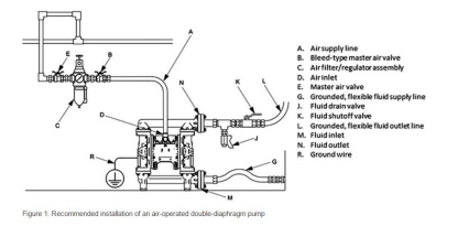
the outlet fluid pressure. Too little back pressure may cause the pump to run inefficiently because the ball checks may not check as quickly. Too much back pressure can cause the pump to stall, if the fluid pressure overcomes the air pressure to the pump. To control the performance (flow and pressure) of an AODD. It is important to have an air regulator assembly installed to control the incoming air pressure (see Figure 1, C). Installing the correct air line size with an air regulator will solve the most common installation problem found with AODD pumps.

Step 2. Inspect for Muffler Icing and Restrictions

Diaphragm pumps can generate high decibel levels at full speed, which is why mufflers are included and recommended
at install. The AODD air motor requires compressed air to operate. As the compressed air enters the air valve and is channeled through the pump center section to exhaust through the muffler. Rapid changes in temperature occur. At the muffler exhaust, air temperature is well below freezing and can cause icing-related issues, increasingly common in humid environments. If your pump is operating erratically, or if the inlet air has high levels of moisture. Or you see frost on the outside of your muffler, these are all indications you are having an issue relating to icing that is decreasing your pump efficiency. Suggested below are solutions you may implement to eliminate these issues and restore your pump performance.

 Decrease the air pressure to the pump.
 Increase size of pump to operate at lower speed (i.e., lower air pressure).
 Exhaust the air to a remote location via an exhaust port tube.
 Add an air line filter with a water catcher and drain to collect condensation.
 Install an air line heater, raising the exhaust air temperature above freezing.
 Adjust pressure dew point temperature with an air compressor dryer.

Step 3. Inspect Sealing Surfaces for Leaking 

Leaking is a very common problem in all types of pumps. But there are some simple fixes to ensure the fluid stays in your AODD pump and not on the ground. First, it is important to know that pumps, especially plastic pumps, need to be
torqued to the manufacturer’s recommended rating. Reason being, materials relax over time. Often referred to as cold flowing. Which can cause sealing surfaces to loosen and create leak paths. Always refer to the pump manual for torque values. And follow the bolting patterns illustrated to reduce the threat of leakage. A wise maintenance technician once said, “There are two types of pumps – those that leak and those that are going to leak.” Reuse of PTFE O-rings is another cause of leaking at sealing surfaces. PTFE is a versatile material, but one of its downfalls is resilience. Once a PTFE O-ring has been compressed, it is not capable of regenerating its original shape. So replace all pump PTFE O-rings when servicing an AODD pump. After properly torqueing your pump per manufacturer recommendations. And ensuring all sealing O-rings have been replaced after service, your AODD should be leak-free.

Step 4. Ensure Proper Tubing and Piping Size 

Pump inlet and outlet fluid port diameters vary based on the flow rate required. It is critical that inlet and outlet hose sizes match the size of the pump. Of primary concern is the risk of cavitation. And the negative effect it has on the pump, causing more frequent repairs and higher maintenance costs. For example, if a 1 inch pump has a ½ inch inlet hose connected. The pump will not be able to operate at full capacity without the risk of cavitation. This risk increases dramatically as the desired fluid viscosity rises. In this example, the 1 inch pump should have a 1 inch inlet and outlet hose attached to avoid cavitation. And more frequent, costly repairs. It is also recommended that an AODD pump be installed with a flexible inlet/outlet connection rather than being hard plumbed. As pump speed increases, vibration increases. As vibration increases, the risk of loosening a hard plumb connection increases, creating the potential for leaking.
Step 5. Slow the Pump Down to Prime 

AODD pumps are popular when self-priming is required. Creating a low pressure zone, less than the atmospheric pressure of 14.7 psi. Inside the fluid bowls is how the AODD pump draws fluid. If the air pressure supplied to the pump is too high. This will cause the pump to changeover too quickly and not allow enough time for the fluid to be drawn into the pump. To solve this priming issue. Use the air regulator to decrease the air pressure entering the air valve and slow down the pump. Once the pump speed has been reduce. And the fluid has been provided enough time to enter the pump, you can increase the air pressure and operate the pump at a faster speed.

Step 6. Clear any Fluid Line Restrictions 

The last step to ensure optimal pump performance is to clear any fluid line restrictions. These restrictions create back pressure that may negatively affect the pump. And potentially create cavitation that will increase frequency of maintenance. Things to look for at both the inlet and outlet of the pump:
 Closed or partially closed valves
 Clogs or kinks in the line
 Too much hose or length of distance

Conclusion 

These quick fixes will solve most of the common problems you may encounter with an AODD pump. Remember to listen to the pump. Many times, carefully listening to the pump operate will tell you what you need to do to reach optimum pump performance levels. Listen for erratic operation, which may be caused by an inlet hose that is too small. Or a problem relating to icing. If you hear what sounds like gravel running through the pump. Or you see flashing around the manifold elbows, you are cavitating and need to correct the inlet or outlet tubing size. Or reduce the pump speed to minimize unnecessary maintenance. Keep an eye out for kinks in your inlet and outlet lines. Or any valves that could be closed or restricted. With these tips, you will achieve top performance out of your AODD pump and spend less time trying to figure out problems and more time pumping.

If you want more information, contact us by phone or email. 

Pumping Pet Food – Case Study

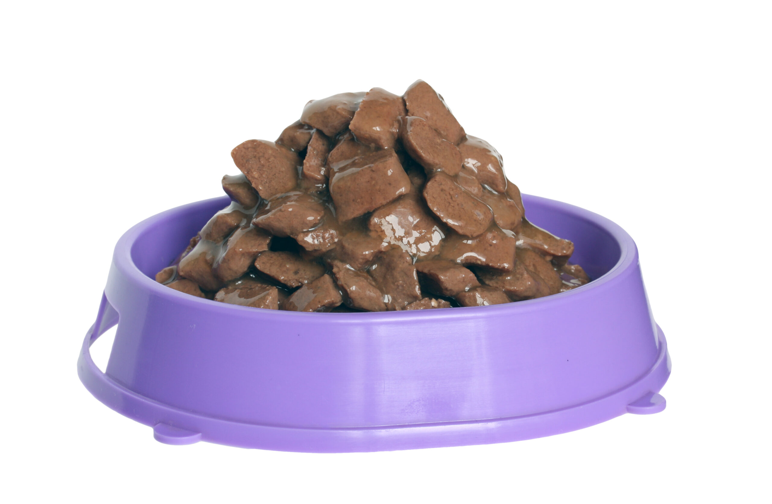
A pet food manufacturer that we work with typically processes a number of meat slurries made of white fish, lamb, chicken, duck, turkey, etc. Due to the different meats and the fact that these slurries are kept in tank hoppers at 40 degrees F or colder, the viscosity of each slurry created pumping issues. The customer had used PD pumps with some success, but they were having to replace or repair these pumps frequently. They wanted a different solution that would minimize maintenance and allow them to pull the meat slurry out of the hoppers. The customer had used PD pumps with some success, but they were having to replace or repair these pumps frequently. They wanted a different solution that would minimize maintenance and allow them to pull the meat slurry out of the hoppers.
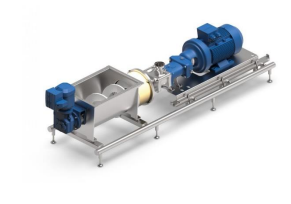
The M.G. Newell account manager thought that a twinscrew pump would be a good solution. In reviewing the case study about The Chocolate Situation, he contacted the pump manufacturer. They brought in a demo pump to try on the meat slurry. The twin screw pump was able to push the slurry through the 4” line. It was also able to suck the slurry from the hopper.

After the trial, the customer upsized to a 5” inlet on the pump to further improve the suction capabilities on this high-viscous slurry. The pump was sized to reflect a flow rate of 18 gpm with a 10HP gear reducer. This sizing decision, as seen in The Chocolate Situation – Case Study, will pump a meat slurry up to 23,000 cps. The customer is currently evaluating the pump on one of their 4 hoppers. If the pump continues to perform, they’ll be putting a twin-screw pump on the other 3 hoppers as well. Want to learn more about how twin-screw pumps work? Are they the right solution for your process? Click: Twin-Screw Pumps

If you want more information, contact us by phone or email. 

Pump Selection and Specifications

Pump Selection Criteria 

For sanitary processing, quick and efficient cleanability is critical when choosing a pump. To ensure a hygienically and microbiologically perfect condition of the final product, high standards apply to centrifugal and PD pumps with regard
to hygiene and cleaning requirements. The surface finish influences the cleanability of pump parts. Cleaning times will decrease with improved surface finishes. Pumps for food, beverage or pharmaceutical industries are constructed of 316L stainless steel or alloys which provide a homogenous, pore-free surface. The product chamber should have no gaps or dead ends. Seal rings clamp in a way that they clean by the CIP solution. Non-metallic seals are typically made of NBR, EPDM, PTFE or FPM.1

The main purposes for creating sanitary design in pumps are to:
· make sanitation programs faster;
· make sanitation programs more efficient;
· make sanitation programs more economical;
· help prevent product adulteration;
· help satisfy regulatory requirements;
· help satisfy consumer/customer audits, demands and requirements.

Additionally, accrediting organizations, such as 3A, EHEDG, and the FDA, publish guidelines meant to specify the
technical requirements of pumps and other processing equipment. Full guidelines can be found on these organizations
websites.

Pump Specifications and Selection 

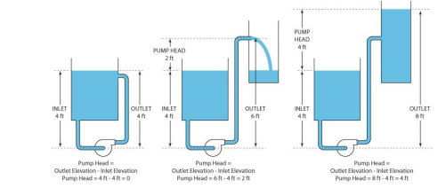
Pumps are commonly rated by horsepower, capacity or flow rate (US gallons per minute), outlet pressure (defined as meters or feet of head), and inlet suction (defined as suction meters or feet of head). The head can be simplified as the number of feet or meters the pump can raise or lower a column of water at atmospheric pressure.

Total Suction Head

where:
hs = static suction head
> 0 for flooded section
< 0 for flooded section
hfs = pressure drop in suction line
ps > 0 for pressure
ps < 0 for vacuum
ps = 0 for open tank

NBR – nitrile rubber; copolymer of butadiene and acrylonitrile; EPDM – Ethylene propylene diene rubber; a terpolymer of ethylene,
propylene and a diene-component; FPM – fluorinated propylene monomer; commonly sold under the trade name Viton®; PTFE –
polytetrafluoroethylene elastomer; commonly sold under the trade name Teflon®

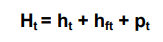
Total Discharge Head

where:
ht = static discharge head
hft = pressure drop in discharge line
pt > 0 for pressure
pt < 0 for vacuum
pt = 0 for open tank

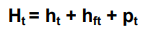
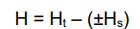
Total Head

where:
Ht = total discharge head
Hs = total suction head

From an initial design point of view, engineers often use a quantity termed the specific speed to identify the most suitable pump type for a particular combination of flow rate and head. Therefore, to ensure you choose the right pump for the application, the following is a list of questions you will need to answer.

Material Properties
What is the material being pumped?
What is the material viscosity?
What is the material density or specific gravity?
What is the particle size?
What is the temperature of the material?
Is the material abrasive?

Process Conditions
What is the desired flow rate?
Where is the feed tank relative to the pump?
What is the suction lift distance?
What is the head pressure?
What is the discharge distance?
What is the inlet and outlet hose diameter?

Other Considerations
What certification is required (FDA, 3-A, EHEDG)?
Will COP or CIP use it? 
What is the desired price range?
What is the pressure of the shop air?
Who will clean and service the pump?
What special applications to consider?

With these questions and answers in hand, you can discuss the best pump choice with one of our engineers.

If you want more information, contact us by phone or email. 

Day in the Life of a Control Systems Engineer

Take a look behind the scenes of a Day in the life of a Control Systems Engineer – Raymond Bennett 

What is a typical day for a control systems engineer at M.G. Newell?

My typical day revolves around project management from the controls perspective. I balance and manage multiple projects, all with unique challenges and constraints. This project management manifests in customer correspondence trying to determine the best solution for their needs, cooperating with internal team members to ensure that our approaches align constructively with one another to facilitate what our end user not only needs but also wants, and of course, what I love most, designing and creating unique solutions to unique challenges. When I am not waist-deep in project work, I spend any spare free time taking advantage of any trainings or research I can. Our industry is constantly evolving, and we as controls engineers must constantly evolve with it.

 If someone is interested in becoming a control systems engineer, what is one piece of advice you’d give them?

Be Curious Always.

No degree is a good substitute for wanting to learn and know—every great engineer I have had the pleasure of working with has wanted to know. Having answers is never as good as being able to find the answers.

What is your favorite thing about your job?

I get paid to solve complex puzzles that change day by day and sometimes hour by hour. Every time I think I have seen it all, I am greeted with another new brain teaser. I also have the opportunity to collaborate with fellow engineers, technicians, and fabricators every day. Which enriches my life with fresh perspectives and valuable lessons that I would not otherwise encounter. Or in less flowery language, I get to do the work I love with people I like!

How long have you been a control systems engineer at M.G. Newell, and what education or background did you have to have to get this job?

I have been with Newell since November of 2024. Coming from a diverse background of manufacturing, robotics, machine vision, and controls that I believe aligned with our goal to venture into more non-process projects. Some of the other selling points that led to my hiring were less my technical capabilities. More so from my appetite for growth and continuous improvement. Originally went to school for film production but veered into electronics engineering technology shortly after starting my academic career. Because of how interesting I found the multidisciplinary curriculum. Academic pursuits with a bachelor’s degree in electrical engineering from FSU. I have consistently found that my associates have served me better from a practical standpoint,. But my bachelor’s has gifted me with boundless resourcefulness in the face of confusion.

Pump Repair Training – Case Study

Pump Repair Training – Case Study 

A customer was having a difficult time with positive displacement pumps needing frequent and costly repairs. After discussions with the plant engineer and sanitation, we felt we had a good grasp on the cause of the problem.

That is where Pump Repair Training comes in. 

The plant had experienced a change in personnel over the last 3 – 6 months on both the sanitation and maintenance staff. Some of the basic steps in disassembly and reassembly had not been properly performed along with missing preventive maintenance steps. The pumps were able to perform, but damage was occurring causing inefficiencies and expense in the upkeep.
Preventative Maintenance

We review our findings with the plant engineer. We don’t suggest a new pump. Instead, we determine that a “refresher” training course is needed to make sure everyone knew the proper sequence of assembly and proper preventive maintenance requirements of positive displacement pumps.

The hands-on pump repair training, proves to be the key in getting the process to turn around and reduce the occurrence of breakdown. This has led to lower maintenance cost and more production operating time. We sometimes lose sight of the “basic” practices that keep our operations functioning smoothly. It is very important that routine training programs and PM plans are in place to review equipment procedures that keep your process running smooth, safe, and cost effective.

M.G. Newell and our equipment manufacturers offer plant audits that help assist you in maintaining your equipment and provide training and preventative maintenance programs. We realize in this “challenged” economy that everyone is looking for ways to tighten their process parameters and keep costs down. This is just another way that M.G. Newell makes it work better.

If you want more information, contact us by phone or email. 

Pump Rebuild vs Pump Remanufacture

Pump Rebuild vs Pump Remanufacture

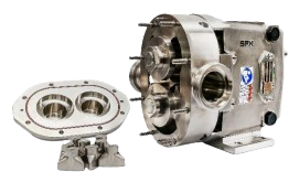
 SPX Flow offers Pump Rebuild and Pump Remanufacture, in conjunction with M.G. Newell, on standard WCB positive
displacement pumps. These options allow you to get a longer life from your pump and reduce the cost of product
ownership.

Pump Rebuild

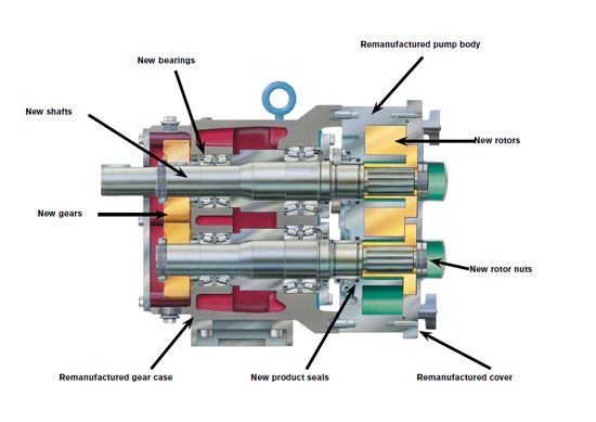
M.G. Newell performs Pump rebuilds in any of our 3 locations – Greensboro, Louisville or Nashville. As a SPX Certified Repair Center, M.G. Newell has qualified factory service technicians on staff with over 30 years of experience. We also invest in equipment, inventory and training to become one of a select group of distributors that are approved. In a rebuild, we pull the shafts, replace the bearings and all wear items. Depending on the amount of wear, we also replace the rotors. Our shop will perform an evaluation of the pump and provide you with an estimate to rebuild your pump. The cost of a rebuild is approximately 50% of the cost of a new pump. The only drawback to a pump rebuild is a slight loss in its original efficiency.

Pump Remanufacture

SPX Flow performs Pump remanufacture at their factory. In this program, they only reuse four parts: the SS cover, body, gear case and gear cover. New and original equipment parts manufactured to factory specifications replace the remaining components. They bore the existing body and make new oversized rotors. This machining is the main difference between a rebuild and remanufacture. Therefore, when complete the pump is back to its original performance specifications and has a new 1-year warranty from SPX Flow. Due to the new oversized body, standard rotors are not used due to potential damage or failure of the pump. Also a pump can be remanufactured two times in its lifetime. Therefore cost of a remanufactured pump is approximately 75% of the cost of a new pump.
If you want more information, contact us by phone or email. 

Pump Problem Solving

Pump Problem Solving – Cavitation 

For all pump application problems, cavitation is the most common issue we encounter. It occurs with all types of pumps – centrifugal, rotary or reciprocating. Cavitation is the formation of vapor cavities in a liquid – i.e. small liquid-free zones (“bubbles” or “voids”) – that are the consequence of forces acting upon the liquid. It usually occurs when a liquid is subjected to rapid changes of pressure that cause the formation of bubbles where the pressure is relatively low. These bubbles are carried along by the fluid and implode instantly when they get into areas of higher pressure.

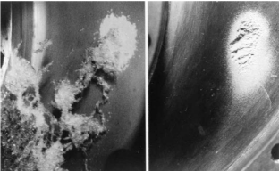
According to the Bernoulli Equation, this may happen when the fluid accelerates in a control valve or around a pump impeller. Cavitation can result in a loss of pump efficiency/flow, noise and possible damage to the pump and/or system. The vaporization itself does not cause the damage – the damage happens when the vapor almost immediately collapses when the velocity is decreased and pressure increased. When a pump cavitates, the vapor bubbles move toward the impeller where they collapse. 

This causes a physical shock which creates small pits on the edge of the impeller. Each individual pit is microscopic in size, but the cumulative effect of millions of pits over a period of time can destroy a pump impeller. Cavitation can also cause excessive pump vibration which damages bearings, wearing rings and seals. Noise is typically the indication that a pump is cavitating. Other indications that can be seen include fluctuating discharge pressure, flow rate and pump motor current. Excessive pump speed and/or adverse suction conditions will probably be the cause.
Suggestions for avoiding or minimizing cavitation:
 Use the 1.5 multiplier for suction tubing (a 2” pump should have a 3” suction tubing and reduce to 2” at the pump)
  – Note – this could cause excessive pump sizing for CIP flow rate. This is only recommended when cavitation is a concern.
 Use the 7 to 10 diameter rule for straight tubing. No elbows directly into the pump.
 Fluid viscosity kills – stay under 5 feet per second.
 Maintain a static head as high as possible.
 Reduce fluid temperature, although caution is needed as this may have an effect of increasing fluid viscosity, thereby increasing pressure drop. If cavitation is a concern, it is strongly recommended that you contact an engineer to review your process.

Pressure ‘Shocks’ (Water Hammer) 

The term “shock‟ is not strictly correct as shock waves only exist in gases.

The pressure shock is really a pressure wave with a velocity of propagation much higher than the velocity of the flow, often up to 1400 m/s for steel tubes. Pressure waves are the result of rapid changes in the velocity of the fluid in especially long runs of piping.

The following causes changes in fluid velocity:
• Valves are closed or opened
• Pumps are started or stopped
• Resistance in process equipment such as valves, filters, meters, etc
• Changes in tube dimensions
• Changes in flow direction

Most pressure wave problems are due to rapidly closed or opened valves. For example, when a valve is closed, the pressure wave travels from the valve to the end of the tube. The wave is then reflected back to the valve. These waves gradually weaken due to friction in the tube. Pumps, which are rapidly/frequently started or stopped, can also cause some problems. A pressure wave resulting from a pump stopping is more damaging than for a pump starting due to the fact that a large change in pressure continues much longer after a pump is stopped compared to a pump starting. A pressure wave induced as a result of a pump stopping can result in negative pressure values in long tubes, i.e. values close to the absolute zero point which can result in cavitation if the absolute pressure drops to the vapor pressure of the fluid. When designing pipework systems it is important to keep the natural frequency of the system as high as possible by using rigid pipework and as many pipe supports as possible.

Effects of pressure waves:
• Noise in the tube

• Damaged tube

• Damaged pump, valves and other equipment

• Cavitation.

Slip

Slip occurs in PD pumps when fluids passes from the discharge side back to the inlet side of the pump through the pump clearances. It is the difference between the theoretical displacement and the actual displacement. Slip is caused by three factors:
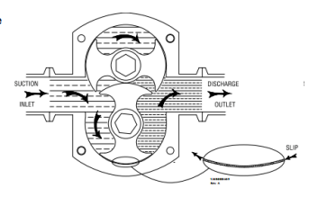
 Viscosity – Slip will decrease as fluid viscosity increases; the
reduction eventually reaches a point called “zero slip”.
 Pressure – Slip will increase with pressure increases
 Clearance – Increased clearances will result in greater slip.
The size and shape of the rotors will be a factor.

If you want more information, contact us by phone or email. 

Pump Pressure Issues – Case Study

Pump Pressure Issues – Case Study

Inconsistent product output? Breaking pipe hangers and ferrules?

These system hammer issues can often be traced back to pump and pressure issues.

A producer of ingredients for human food and animal nutrition was having major issues in their process. They were inducting powdered maltodextrin into their process to form a starch slurry. During the maltodextrin induction process, air was getting into their PD pump. It was then pulled into a centrifugal booster pump that was pushing the slurry vertical 40 feet into a tank. They were experiencing low flow rates (30-60 gpm) and high pressures (>120 psi).
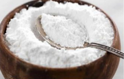
The product was building up in the pump housing seals. Product output was inconsistent. They were breaking ferrules and hangars. They had long periods of downtime. Operators were trying to overspeed the motors on the pumps to increase production rates.

The M.G. Newell salesman recommended that the customer consider a twin-screw pump. Twin-screw pumps can handle highly viscous products such as starch slurries. The design minimizes shearing in the product while still handling high pressures and higher speeds. Most importantly, the pump can handle any air that may be pushed into the line from the powder induction system. The customer removed the PD pump and the centrifugal booster pump and replaced them with 2 twin-screw pumps. They also switched 2” tubing and ball valves to 3” tubing and added an overpressure valve after the first pump.
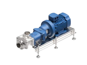
After one month, the customer loves the new process improvements. They are maintaining a more consistent flow rate of 80-110 gpm and lower pressures of 60 psi. Production increased by 26% with more consistent product and a quieter production area. Maintenance and downtime decreased by 30%.

If you are frustrated with extended maintenance and downtimes, give us a call. We are happy to share our experience with you. Contact one of our associates to see how We Make It Work Better.
If you want more information, contact us by phone or email. 

The Pump Overview Part 2

The Pump Overview Part 2

As we continue the Pump Overview series, let’s review a few basic principles of pumps.
Pressure, friction and flow are three important characteristics of a pump system. Pressure is the driving force responsible
for the movement of the fluid, expressed as pounds per square inch (psi). Friction is the force that slows down fluid
particles. Flow rate is the amount of volume that is displaced per unit time, usually expressed as gallons per minute.
Pumps are typically classified by the way they move fluids. For the sanitary industry, we will only focus on positive
displacement pumps and centrifugal (or rotodynamic) pumps. Positive displacement pumps include single and double
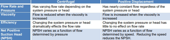
rotary lobe pumps and diaphragm pumps. The table below outlines a few of the basic differences between these pumps.

Centrifugal pump

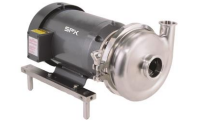
A centrifugal pump is a rotodynamic pump that uses a rotating impeller to increase the pressure and flow rate of a fluid. Centrifugal pumps are the most common type of pump used to move liquids through a piping system.

A typical centrifugal pump has five basic parts:
1. Casing also known as the volute, is the outside visible part of the pump. For sanitary processing, the casing is typically a heavy-walled 316L stainless configured in a spiral design to even out flow and minimize turbulence. The end cover is clamped on and can be easily removed for access to the impeller.

2. Impeller The impeller is the main rotating part that provides the centrifugal acceleration of the product. The impeller can have an open or closed vane. Generally closed vane impellers develop higher pressures but have a lower capacity. Open vane impellers develop lower pressure but have a higher capacity. It is attached to the shaft and rotates inside the casing at the speed of the shaft. The design is balanced to prevent vibration.
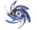
3. ShaftThe shaft rotates insides the casing at the speed of the motor and transfers the torque from the motor to the impeller. The shaft is typically made of 316L stainless.

4. BearingsThe bearings support the shaft and keep it in alignment so that it does not wobble inside the casing and prevents it from touching the casing.

5. Seals and/or PackingThe seals are the essential area in terms of hygiene as they prevent the product from leaking back inside the pump or outside of the pump when it is under pressure. Pumps can have either single-seal or double-seal arrangements.


How does a centrifugal pump produce pressure?

The fluid enters the pump impeller along or near to the rotating axis and is accelerated by the impeller, flowing radially outward or axially into a diffuser or volute chamber, from where it exits into the downstream piping system.
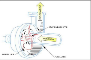
The velocity of the fluid is also partly converted into pressure by the pump casing before it leaves the pump through the outlet. Pressure is produced by the rotational speed of the impeller vanes. The speed is constant. The pump will produce a certain discharge pressure corresponding to the particular conditions of the system (for example, fluid viscosity, pipe size, elevation difference, etc.).

If changing something in the system causes the flow to decrease (for example closing a discharge valve), there will be an increase in pressure at the pump discharge because there is no corresponding reduction in the impeller speed. The pump produces excess velocity energy because it operates at constant speed. The excess velocity energy is transformed into pressure energy and the pressure goes up.

Centrifugal pumps are typically used for large discharge through smaller heads. Centrifugal pumps are most often associated with the radial-flow type. However, the term “centrifugal pump” can be used to describe all impeller type rotodynamic pumps.

Therefore, the main factors that affect the flow rate of a centrifugal pump are:
 Friction, which depends on the length of pipe and the diameter
 Static head, which depends on the difference of the pipe end discharge height vs. the suction tank fluid surface height
 Fluid viscosity, if the fluid is different than water.

Typically, centrifugal pumps are selected for:
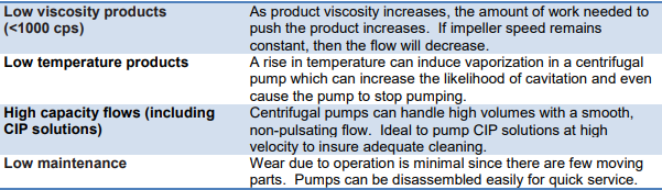
If you want more information, contact us by phone or email. 

The Pump Overview Part 1

The Pump Overview Part 1 

A pump is simply defined as a device that raises, transfers, delivers, or compresses fluids or that attenuates gases especially by suction or pressure or both. Pressure, friction and flow are three important characteristics of a pump system. Pressure is the driving force responsible for the movement of the fluid. Friction is the force that slows down fluid particles. Flow rate is the amount of volume that is displaced per unit time.

Pumps are typically classified by the way they move fluids. For the sanitary industry, we will only focus on positive displacement pumps and centrifugal (or rotodynamic) pumps. Positive displacement pumps include single and double rotary lobe pumps and diaphragm pumps. The table below outlines a few of the basic differences between these pumps.

Positive Displacement Pump

A positive displacement (PD) pump makes a fluid move by trapping a fixed amount and forcing (displacing) that trapped volume into the discharge pipe.

Some positive displacement pumps use an expanding cavity on the suction side and a decreasing cavity on the discharge side. Liquid flows into the pump as the cavity on the suction side expands and the liquid flows out of the discharge as the cavity collapses. The volume is constant through each cycle of operation.

Positive displacement pumps, unlike centrifugal or roto-dynamic pumps, theoretically can produce the same flow at a given speed (RPM) no matter what the discharge pressure. Thus, positive displacement pumps are constant flow machines. However, a slight increase in internal leakage as the pressure increases prevents a truly constant flow rate.

For each revolution of the pump, a fixed volume of liquid is moved regardless of the resistance against which the pump is pushing. Therefore, a positive displacement pump must not operate against a closed valve on the discharge side of the pump, because it has no shutoff head like centrifugal pumps. A PD pump operating against a closed discharge valve continues to produce flow and the pressure in the discharge line increases until the line bursts, the pump is severely damaged, or both.

A relief or safety valve on the discharge side of the positive displacement pump is therefore necessary. The relief valve can be internal or external. The pump manufacturer normally has the option to supply internal relief or safety valves. The internal valve is usually only used as a safety precaution. An external relief valve in the discharge line, with a return line back to the suction line or supply tank provides increased safety. PD pumps are designed with very small clearances between the rotating lobes and the stationary parts to minimize leakage (slippage) from the discharge side back to the suction side. They are designed to operate at relatively slow speeds to maintain these clearances; operation at higher speeds causes erosion and excessive wear, which result in increased clearances with a subsequent decrease in pumping capacity.

When would you choose a PD pump? Typically, PD pumps are selected for the following scenarios:

Diaphragm Pumps

A diaphragm pump (also known as a Membrane pump, Air Operated Double Diaphragm Pump (AODD) or Pneumatic Diaphragm Pump) is a positive displacement pump that uses a combination of the reciprocating action of a rubber, thermoplastic or Teflon® diaphragm and suitable valves either side of the diaphragm (check valve, butterfly valves, flap valves, or any other form of shut-off valves) to pump a fluid. This implies that the pump will deliver a specific amount of flow per stroke, revolution or cycle.

Air operated double diaphragm pumps have the following components:
 Air chambers: The pump has two chambers, one on the left side and the other on the right side of it. These chambers let the compressed air flow in and out of it.
 Air valve: The compressed air is directed to air chambers with the help of air valves. These have a valve cup and a valve plate. Air valves make sure that the compressed air enters the air chambers and leave from it through the exhaust port

 Check valve: There are four fluid check valves in a double
diaphragm pumps. Two of them are inlet check valves while the other two are outlet check valves. The flow of liquid in the fluid housing and manifolds is controlled by these check valves.
 Fluid housing: Each pump has fluid housing, one at each side of the pump. As the name implies, fluid housing is that part which holds the fluid and makes it flow through the pumping mechanism.
 Inlet manifold: Fluid enters the pumping container via the inlet manifold and flows evenly to the left and right fluid housing. This mechanism makes the distribution of fluid equal so that both fluid housings remain in operation.
 Outlet or Discharge manifold: When the fluid is coming out of the container, it passes through a couple of components. First, the fluid passes through one of the exit check valves and then this check valve directs the fluid to the outlet manifold to finally exit the container altogether.
 Diaphragms: The air operated double diaphragm pump obviously has two diaphragms in it. The diaphragm is actually a kind of a separation sheet in between the air chambers and fluid housings. The diaphragms are good enough to adjust
themselves according to the rise or fall of the air pressure, as the condition may be. Besides, the two diaphragms are allied with a shaft.
 Muffler: The objective of muffler is to control noise of the exhaust air. There are multiple mufflers available that offer several levels of noise reduction to ensure effective and efficient pumping operation.
 Exhaust port: The exhaust port is the final exit point in the pump.

How Does An Air Operated (Double) Diaphragm Pump Work?

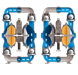
Using compressed air as the resource to operate, double diaphragm pumps are meant for low pressure activities mainly. A vacuum is formed inside the pump casing each time the diaphragm is raised. This allows the inlet valve to open and seals the discharge valve thus allowing water and air to enter the pump. Whenever the diaphragm is lowered the resulting pressure seals the inlet and opens the outlet valve purging the pump housing of water and air.

In summary, the process is given below:
1. Chambers are filled with fluid and then emptied through an ongoing process. This is done through inlet and outlet manifolds.

2. The shaft joining the left and right diaphragms in each chamber enables them to move to and fro continuously.

3. Compressed air is directed to one of the diaphragms.

4. Eventually as the suction stoke occurs, the lower ball valve opens and the top one closes. Simultaneously, fluid enters the chamber through the inlet manifold.

5. When air enters the other diaphragm, the top ball valve opens and the lower one is closed. This allows the fluid to exit through the outlet manifold.

6. The same process repeats with the other chamber and it goes in cycles between the two chambers

When would you choose a diaphragm pump? 

The compressed air design gives diaphragm pumps the ability to run without electric power. Otherwise, diaphragm pumps offer many of the same benefits of a traditional lobe-style PD pump. They have a low initial cost, are easy to maintain and simple to install. They can handle shear-sensitive products and have the ability to process delicate materials without damage to the product. Diaphragm pumps are self-priming with excellent flow rates. Common applications include ingredient unloading (tote or drum unloaders), filler feeding and batch metering processes.

Diaphragm pumps:
• have good suction lift characteristics
• are able to handle a wide range of pressures and can deliver flow rates up to 300 gpm, dependent on the effective working diameter of the diaphragm and its stroke length.
• have good dry running characteristics.
• can be up to 97% efficient.
• have good self-priming capabilities.
• can handle highly viscous liquids (up to 1,000,000+ cps). A viscosity correction chart can be used as a tool to
help prevent under-sizing AODD pumps.

If you want more information, contact us by phone or email.