Optimize Centrifugal Pump System Efficiency

Optimize Centrifugal Pump System Efficiency 

Take steps to reduce energy consumption, lower maintenance costs and improve process control 

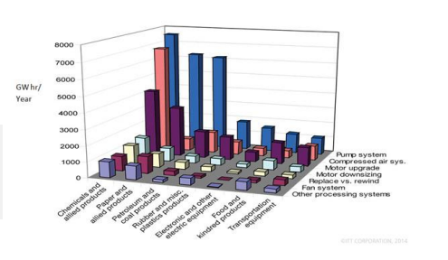
Most chemical plants are working to become more energy efficient. Companies are implementing energy management software, installing occupancy sensors throughout plants to help lower electricity bills, and even changing times of operation to use less power at peak load to avoid the associated higher rates. One of the best ways to save energy is to focus on motor-driven pumps. Pumps consume more energy in chemical plants than any other category or type of rotating equipment. The average annual spending on pump maintenance and operations is approximately 50% greater than that of any other rotating machine, according to a recent study by the FiveTwelve Group. Companies that operate large numbers of pumps usually recognize the high energy costs as well as the impact pumps have on reliability and process control. However, too many organizations focus on these factors separately when, in fact, they are closely linked. A recent report on the use of motor efficiency technologies by the U.S. Department of Energy’s Industrial Technologies Program (ITP) contained an in-depth analysis of energy use and savings potential by market segment and industry. The report identified centrifugal pumps as the largest consumers of motor energy (Figure 1). Also, among all rotating assets in the plant, process pumps had the highest overall potential for electrical energy savings.

A separate Finnish Research Center study of centrifugal pump performance found that the average pumping efficiency was less than 40% for the 1,690 pumps reviewed in 20 different plants across all market segments. That study also revealed that 10% of the pumps were operating at less than 10% hydraulic efficiency. Considering this sizable efficiency loss, you can expect that from 10% to 20% of the pumps in any continuous process plant are candidates for optimization. More than likely, the real number is much higher. In the largest continuously operating process plants, opportunities for cost reduction—when all aspects of the system are considered —can easily represent millions of dollars and, thus, significantly impact the bottom line. Efforts to improve reliability and achieve optimization of pumping systems invariably involve addressing what is called the
―energy and reliability nexus.‖ In general, mechanical energy in excess of that required for moving process fluid through the pipes is manifested as vibration, heat and noise. This excess energy becomes a destructive force that undermines
pump and process reliability. As a result, pump systems routinely have the highest overall maintenance cost compared to other motor systems, including control valves, instrumentation and other types of process control equipment. In addition, pumps and valves are the primary process leak paths for fugitive emissions. 

LIFECYCLE ANALYSIS

Today, companies increasingly are relying on lifecycle costing (LCC)
for selecting an optimal solution to create economic and
environmental value over the life of a system. Using a lifecycle-cost
perspective during initial system design will minimize operating
costs and maximize reliability. For pump systems, using LCC makes
particular sense because the initial purchase price typically
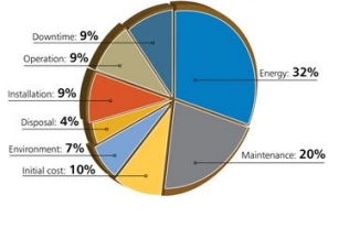
represents only about 10% of long-term costs.

A LCC analysis assesses the cost of purchasing, installing, operating, maintaining and disposing all the system’s components. Determining the LCC of a system involves using a methodology to identify and quantify all the components of the LCC equation. For instance, the equation provided in the Hydraulic Institute’s ―Pump Life Cycle Costs: A Guide to LCC Analysis for Pumping Systems‖ includes terms for initial cost or purchase price (e.g., the pump, pipe, auxiliaryequipment); installation and commissioning costs (including training); energy costs (predicted for entire system, including controls); operating costs (labor man-hours for normal system supervision); maintenance costs (e.g., parts, tools, labor man-hours); downtime costs (loss of production); environmental costs (leakage losses and permit violations); and decommissioning costs (disassembly and disposal).

Energy consumption is a major element in pump lifecycle costs. Because excess energy consumption leads to higher maintenance costs, these two elements combined typically dominate total lifecycle cost. Thus, it’s important to determine
the current cost of energy and the expected annual escalation in energy prices over the system’s projected life, along with labor and material costs for maintenance.

Today, pump and automation suppliers, either individually or in partnership, provide customized services to help customers identify, qualify and quantify a pump system’s cost of ownership. Moreover, forward-thinking vendors are viewing their offerings as a holistic package of goods and services, providing the appropriate mix of products, information, training, customer service and personal attention to fully address the customer’s needs.

PROPER SIZING

Improper sizing often is the major culprit when it comes to pump inefficiency. Over-sizing of process pumps frequently occurs because parameters aren’t fully defined as the pumps are being specified.

Ideally, every pump should operate at its best efficiency point (BEP) at all times but often this isn’t a likely scenario. To maximize the return on an efficiency program, it’s important to know which pumps are most in need of attention and whether they possess far more or less flow capacity than optimum.

Consider, for instance, a pump for delivering 5,000 gpm of water at 100 ft. The right-sized pump may offer an efficiency of 70% and require 180 hp (133 kW). If, instead, the pump system is over-sized (excess capacity) and throttled (lower efficiency), efficiency may drop to 40% and brake horsepower may rise to 315 hp (232 kW). That difference of 135 hp or 99 kW (75% excess energy) will contribute to unreliability and poor control performance that continuously degrades over time.

Excess energy moving through the system often gives rise to tell-tale symptoms — including a highly throttled control valve in combination with pronounced pipe movement, or even a vibrating catwalk attached to plant infrastructure that’s
used to brace the throttled pump. Cavitation inside the pump, control valve or piping itself is a clear indication that hydraulic turbulence or instability exist.

If the system’s flow is too high coming out of the pump, some users choose simply to throttle the flow using a valve on the discharge side. This is a very inefficient and costly way to configure a system. It increases energy costs for operating the pump, reducing the operating life of the equipment and boosting downtime. Pumps are designed for specific hydraulic flow ranges. When a pump is operating optimally at its BEP, liquid flow is constant and radial forces acting on the impeller are balanced and minimized. As the pump is operated further away from its BEP, the radial and axial loads on the impeller rise. These increased loads can cause shaft deflection, which raises stress on the pump’s bearings and mechanical seal and accelerates the likelihood of pump failures.

MONITORING AND MAINTENANCE

Pump equipment condition is the most important factor for overall system efficiency. Today, various methods exist to monitor temperature, vibration and general health of rotating equipment —and diagnostics are becoming easier.

Maintaining reliable pump operations requires deploying a robust program that combines monitoring basic machine-health data in addition to pump operating conditions. The program should address four areas:

1. Pump performance monitoring. To better understand how a pump is performing, monitor five parameters — suction pressure, discharge pressure, flow, pump speed and power. Regularly checking suction and discharge pressure is essential for determining the total dynamic head (TDH) and the available net positive suction head (NPSHa), keeping the pump efficient throughout use. Permanent flow meters often are the best option for effective flow monitoring. If you’d like a temporary solution, go with clamp-on flow meters. For power measurements, consider using more than just transducers for monitoring. Assess factors such as input voltage, power factor and motor efficiency to accurately determine the actual shaft horsepower being transmitted to the pump. Pump speed also plays a role —the change in power should be proportional to pump speed.

2. Vibration monitoring. The vibration level of a pump directly relates to where it’s operating on its associated performance curve. In essence, high vibration levels indicate poor performance. To avoid future issues, take a vibration reading when a
pump is installed. This initial reading provides the baseline for future monitoring.

3. Bearing temperature monitoring. The best way to monitor pump bearing temperature is via a measuring device that contacts the bearing’s outer race. However, there are other, less invasive options, too. One alternative is to use an
infrared gun to obtain a temperature reading from the outside of the bearing house.

4. Visual inspections. To detect visual symptoms of pump distress such as cracking, leaking or corrosion, conduct frequent visual inspections; they are an inexpensive way to help save your system from future failures.

PROCESS CONTROL
According to a study of 300 plant energy audits by Emerson Entech, the majority of basic control loops involving pumps (or a set of devices designed to manage the behavior of other devices in a system) actually increase process variability.
The primary reason is improper sizing of the pump, control valve and piping — namely, not selecting them in concert to ensure optimum performance — which typically makes tuning the control loop difficult. Automatic control constantly
degrades over time as a result of pump and valve mis-sizing issues; as a result, control loops often are switched into manual mode to stabilize the process.

Other studies show a high percentage of control loops actually operate in manual mode. A benchmarking report by Honeywell LoopScout of 115 separate facilities across all market segments revealed that, at the worst performers, up to 60% of control loops were ―bad actors,‖ with many of those operating in manual mode.

Once you’ve picked a pump to optimize, you can consider a range of mechanical and digital options to help regulate your pumping assets.

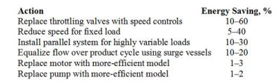
Mechanical and control modification systems. As Table 1 indicates, using a speed control to help vary speed linearly with an accompanying increase or decrease in horsepower consumption can provide sizable energy savings. 

Even a small speed reduction could lead to a 30% drop in power consumption. Alternatively, impeller trims (altering the impeller diameter) can change horsepower consumption at a squared rate —offering significant power decreases but not ones as large as from speed changes.

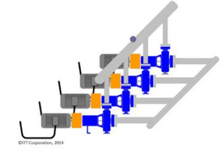
Another mechanical option is installing a parallel system to cope with fluctuation in flow or demand rates. By installing two similar pump systems with parallel piping to handle variable flow rates, plant operators can deal with rates that one pump can’t support alone. Although this may seem like an obvious solution, if the load increases more than the pump was designed to handle, the original pump may be running inefficiently from the beginning.

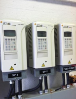
Electronic control systems. Digital technologies, such as electronic inverters, electronic-only variable frequency drives
(VFDs) and variable speed drives (VSDs) that include mechanical devices in addition to electronics, can alter the speed of the pump motor to help improve efficiency.

A VFD is an electrical system that controls motor speed by varying the frequency supplied to the motor. The drive also regulates the output voltage in proportion to the output frequency to provide a relatively constant ratio of voltage
to frequency (V/Hz), as required by the characteristics of the AC motor to produce torque. In closed-loop control, a change in power and frequency supplied to the motor alters its speed, thus compensating for a change in process demand. This
means greater process control and system efficiency, with even more intelligence integration.

Modern VFDs are the most efficient method to change pump speed, with up to 98% electronic efficiency. The simplest of these is the soft starter, a solid-state motor starter that’s used to start or stop a motor by reducing the voltage to each of
its phases, gradually increasing the voltage at a fixed frequency until the motor gets up to full voltage/speed. Motors, especially low-voltage ones, have a high initial current (amp draw) when first turned on; this can cause voltage
fluctuations and affect the performance of other circuits. Voltage spikes also can damage motor windings. To counteract this issue, you can add components in series to control current in-rush upon startup. In addition, it’s crucial for electronic
systems to reside in a climate-controlled environment, which is becoming more common as plants integrate digital systems.

More-advanced VFDs or VSDs utilizing frequency inverters can vary the speed of the pump to match the process flow demand. VFDs offer tremendous benefits, including pump size reductions, lower energy costs and improved efficiency. The U.S. Department of Energy estimates that up to 25% of installed motor systems can benefit from retrofitting VSD technology.

Despite the known benefits of the technology, initially VFD adoption was relatively slow, primarily due to perceived complexity, reliability and electrical issues. However, today’s more mature VFD technology and cable installation practices largely have mitigated these concerns. As a result, VFD implementation on pump systems is on the rise.

CASE IN POINT

When evaluating inefficiencies in a pumping system, it’s important to look for tell-tale symptoms of excess energy moving through various subsystems. Often, inefficiency results from a combination of issues that negatively affect equipment
integrity and surrounding infrastructure.

A vat dilution pump in a chemical process had a 1,180-rpm, 250-hp (187-kW) medium-voltage motor driving a double suction pump. The pump had a 14-in. (35.5-cm) discharge line that branches into three separate lines, each feeding200°F (93°C) filtrate to separate end-user systems. Each of the 10-in. (25.4-cm) branches had its own 8-in. (20.3-cm) control valves that usually were operating in the range of 20% to 40% open. The gaskets between the pump discharge flange and pipe frequently failed. Looking downstream and up to the top of the chemical towers, the pipes on each branch were rattling, leading to an inordinate number of cracks. Such pipe cracks can cause chemical losses in the sewers, environmental incidents and unplanned downtime. All told, the over-sized pump system averaged one day of downtime per month to repair some component or multiple components. These 12 additional days of unplanned downtime cut into production goals, increased costs and reduced profits. In this case, the financial impact exceeded $1 million annually. Added to that, the company suffered negative publicity both locally and nationally.

The primary solution here was implementing VFDs for constant discharge pressure control. The pump system normally consumed around 200hp (149kW), with the end-user valves highly throttled (20%–40% open) and the vibration levels about 0.6 in.(1.5 cm) per second. After VFD implementation, the pump consumes 75 horsepower (56 kW) during normal operation. In effect, the excess 125 horsepower (93 kW), not required to move the fluid, was directly damaging the pump and reducing its reliability.

IMPROVE SYSTEM EFFICIENCY

Using LCC to assess pump systems can lead to substantial performance gains. The amount of excess energy, once identified, will serve as the first step in quantifying the value needed for project justification. Then, predict reliability improvements and use past work orders and computerized-maintenance-management-system repair records to estimate annual maintenance costs avoided. Also, evaluate whether better process control can reduce the costs incurred by material variability. Estimate lifecycle savings based on current costs versus optimized ones. The plant of the future will make calculated decisions based on measurable, long-term operating costs and through identifying potential energy drains.

If you want more information, contact us by phone or email. 

The Chocolate Situation – Case Study

“Life is like a box of chocolates. You never know what you’re gonna get”

Tom Hanks in Forrest Gump 

For one chocolate processor, they sometimes never knew what the chocolate situation was going to be in their plant. They only knew each sweet product brought its own unique challenges. One of our customers manufactures candy bars and protein bars. Common ingredients include melted white and dark chocolate, caramel, liquid sugar, peanut butter, syrup, and some custom flavorings. Each product presents unique demands in processing. For example, one process may require a very thick and abrasive dark chocolate, but then very thin and smooth white chocolate for another.

Due to these variations in product properties, choosing a transfer pump was a headache for the plant. The customer had 4 different brands of pumps in their lines. For each brand, they had 3-4 different sizes and models with different pumping capacities. Each one had a different design and different spare parts, resulting in a large number of spare parts on stock. And maintenance? Maintenance was performed line-specific since most of the pumps were not interchangeable. It was simply a daily headache for the production and maintenance teams.

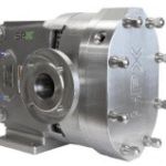
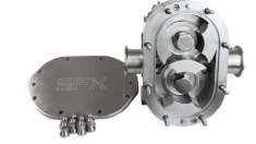
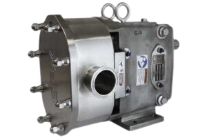
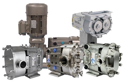
M.G. Newell carefully studied the customer’s process requirements and specifications including temperature, flow rate, product abrasiveness and elastomer compatibility. We were able to standardize the customer’s transfer pumps down to one brand, one model and 3 sizes to handle their entire pump needs. By standardizing on the Waukesha Cherry-Burrell Universal 3 Series of positive displacement pumps, the number of spare items was greatly reduced since two of the 3 sizes share common spare parts.

Also, since the pumps share a common design, maintenance has improved and streamlined. Each technician can work on any process line and pumps can easily be replaced by a same size pump. They’ve also reduced their spend on spare parts by reducing the number of spares in inventory. Simply put, it’s one more way We Make It Work Better.

If you want more information, contact us by phone or email. 

Benefits of using diaphragm pumps for hygienic applications

Benefits of using diaphragm pumps for hygienic applications 

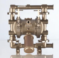
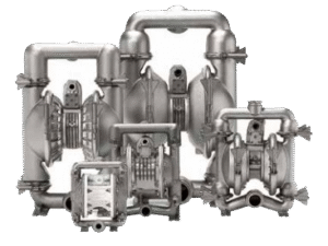
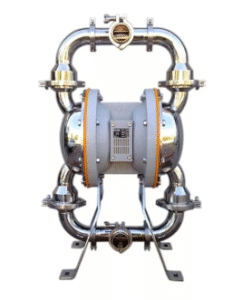
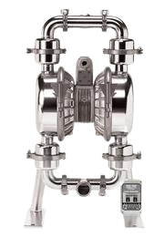
Air Operated Double Diaphragm (AODD) pumps have been part of the industrial pumping scene for more than 50 years. These pumps are extraordinarily good “all-rounders” and boast vital performance characteristics that make them ideally suited to a wide range of hygienic pumping applications.

Applications for AODD Pumps 

AODD pumps are suitable for a host of applications, including raw materials transfer, drum emptying, recirculation, filling machines, mixing and dosing, processing and sampling. They will readily handle viscous liquids as well as fluids containing soft and hard solids such as fruit puree containing seeds and pips. This versatility makes them well suited to pumping many different fluids such as: 

 Yogurts, including various flavorings
 Creamed cottage cheese
 Cream, ice cream mix, syrups and toppings, chocolate coatings
 Margarine and fats
 Spent yeast in breweries
 Mechanically-deboned meat

The pumps have large internal clearances and flow-through which prevents clogging, with the size of solid particles that can be pumped related to the pump size. However they also have gentle pumping action which avoids damage to shear sensitive products. The pumps are capable of pumping viscous fluids since the flow rate is directly proportional to the speed of the pump. When viscous materials are pumped there are friction losses within the pump itself and between the fluid and the walls of the pipe supplying the pump. The pump automatically reduces the pumping rate as viscosity
increases and at the point where the pump can no longer move the liquid, it simply stops without damaging itself. Typically, AODD pumps can move fluids with viscosities up to 20,000 cps.

Using AODD Pumps 

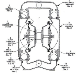
Some of the key benefits offered by AODD pumps are that they are self-priming, will run dry without damage and need no electricity. Self-priming means that the pump is capable of drawing up liquid even when installed above the source liquid level and without having to have any liquid in the pump already. This self-priming characteristic means there are few restrictions on physical placement of the pump and also means that by simply attaching a hose to the inlet, the pump can be used as a “scavenger,” to completely empty containers. In addition, if the supply of fluid runs out, the pump will run dry without any damage to it. Most positive displacement and centrifugal pumps fail if they run dry, frequently because their shaft seals or stuffing boxes may require lubrication or cooling from the pumped fluid.

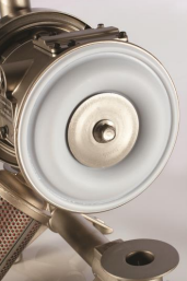
AODD pumps, however, simply run faster when running dry without damage. The pumps are powered entirely from compressed air, and so can be used in applications where electricity is not available or must not be used (hazardous or explosive environments). The pressure from the compressed air moves the two diaphragms inside the pump. These diaphragms form a dynamic seal that converts the pneumatic pressure on one side to a fluid pressure on the other (the fluid to be pumped). Discharge flow rates can be adjusted simply by controlling the air inlet or the discharge flow, making them extremely simple to use, with no complex control systems needed. AODD pumps are very reliable since they have very few moving parts and components that can wear. They are easily dismantled for maintenance or diaphragm replacement. These factors contribute to a low cost of ownership.

Choosing the right pump for the application 

With a wide choice of pump materials and, of course, an extensive range of sizes and pumping capacities from a large number of manufacturers, there are pumps to suit a broad range of hygienic production and transfer processes. Given this huge choice, it can be useful to consult with independent pump suppliers, who are not tied to a particular manufacturer, for advice on the most suitable pump for a given application within the allocated budget.

Meeting Hygiene Standards 
AODD pumps used in hygienic applications are manufactured from 316 grade stainless steel, with diaphragms made from sanitary grade elastomers such as Santoprene®, Buna-N, Viton® and Teflon®. The key factors which determine the suitability of a diaphragm for a particular application are: flex life, the composition of the fluids to be pumped and their effect on the diaphragm, the temperature range that the pump must operate in and the abrasive nature of the media being pumped, including the size of any particulates.
The ability to clean the pumps is also of critical importance, and pumps used in the dairy industry will generally have to conform to the requirements of at least one of the following regulatory authorities:

 FDA (Food & Drug Administration)
 3A Sanitary Standards Administrative Council in the USA
 EHEDG (European Hygienic Equipment Design Group)
 USDA (United States Department of Agriculture)

Cleaning is either carried out by dismantling the pump between batches or carrying out clean–in-place (CIP) procedures. AODD pumps contain fewer moving parts than many other types of pumps and can be easily dismantled for cleaning. Many of the materials used for manufacture will also be resistant to the chemicals used in CIP processes.

If you want more information, contact us by phone or email. 

4 Pump Mistakes You May Be Making

4 Pump Mistakes You Might Be Making 

 
In sanitary processing, pumps are one of the most critical pieces of equipment in the plant. Your company has invested the money in equipment.
Then what? How do you make sure you’re getting the most out of your investment?
Here’s a few common mistakes that companies make.

Choosing the wrong type of pump

A pump is a device that raises, transfers, delivers, or compresses fluids or that attenuates gases
especially by suction or pressure or both. Pressure, friction and flow are three important characteristics of a pump
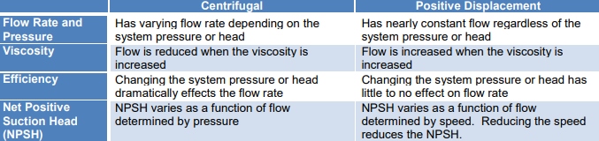
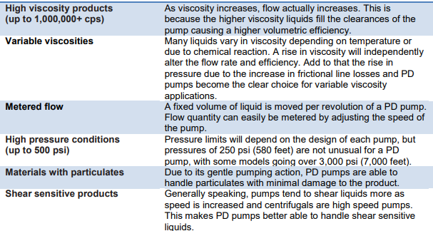
system. Pumps are typically classified by the way they move fluids. In sanitary processing, the most common types are
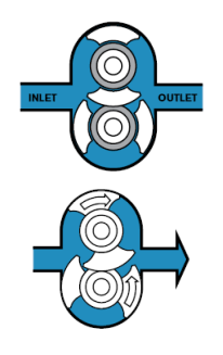
positive displacement (PD) pumps, centrifugal (or rotodynamic) pumps, diaphragm pumps and twin-screw pumps. So
which type is right for your process? That depends on several factors.

Pumps rate by horsepower, flow rate (gpm), outlet pressure (feet of head), and inlet suction (suction feet of head). The head can be simplified as the number of feet or meters the pump can raise or lower a column of
water at atmospheric pressure. From an initial design point of view, engineers often use a quantity termed the specific
speed to identify the most suitable pump type for a particular combination of flow rate and head. Therefore, to ensure
you choose the right pump for the application, the following is a list of questions you will need to answer.

Material Properties 

What is the material being pumped?
What is the material viscosity?
What is the material density or specific gravity?
What is the particle size?
What is the temperature of the material?
Is the material abrasive?

Process Conditions
What is the desired flow rate?
Where is the feed tank relative to the pump?
What is the suction lift distance?
What is the head pressure?
What is the discharge distance?
What is the inlet and outlet hose diameter?

Other Considerations
What certifications are required (FDA, 3-A, EHEDG)?
Will it be used for COP or CIP?
What is the desired price range?
What is the pressure of the shop air?
Who will clean and service the pump?
What special applications to consider?

Selecting the wrong size motor

There are at least three major considerations to keep in mind when sizing a motor to drive a pump:

  • What are the power demands of the pump?
  •  What will typical operation look like for this pump?
  • Will the pump operate on a variable frequency drive (VFD)?

While you don’t want to undersize a motor, the vast majority of motors are design with a 1.15 service factor which will
provide a bit of an insurance policy. Most motors are generally sized at predetermined intervals which means you will need to round up to the next available motor size when determining how large a motor to couple up to a pump. So if the pump power requirements indicate that the motor should be rated for at least 1.5 HP, you’ll have to round up to the next normal motor rating: 2 HP.

It’s important to size a motor properly. Doing so will produce a pumping unit that is more efficient and provides a longer
service life. Failing to size the motor correctly will result in a pumping unit that demands more power than it should or one that produces repeated electric faults and may suffer from premature motor failure.

Operating away from the Best Efficiency Point

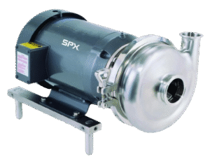
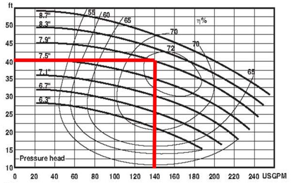
The most common pump in sanitary processes is the centrifugal pump. When selecting a pump, an engineer will refer to a pump performance curve. The Best Efficiency Point (BEP) is a term that identifies an operating region along the pump
performance curve. It is defined at the flow at which a pump operates at the highest or optimum efficiency for a given impeller diameter.

Operating your pump too far to the left or right of the BEP can increase your operating cost and reduce the life of your pump:

  • Cavitation – caused by the formation of vapor bubbles which violently collapse, damaging impeller surfaces and reducing the
  •  time between repairs. It typically occurs when operating too far right of BEP. As the flow increases beyond the BEP, Net Positive Suction Head required (NPSHr) also increases. When this exceeds the Net Positive Suction Head available (NPSHa), cavitation occurs.
  • Vibration – when pumps operate too far right of BEP, excessive vibration can occur. Some may be caused by cavitation. It may also occur due to higher bearing loads associated with the pump operating too close to shut-off conditions. The net effect – bending and damage to the shaft.
  • Reduced bearing and seal life – Cavitation and vibration will increase your maintenance costs as seals and other internal components will wear and need to be changed more frequently. Rotor instability, shaft vibration and/or failure, and higher bearing temperatures all lead to premature breakdown of lubricants and seals.

Not performing regular maintenance

Pumps, like all equipment, need regular TLC to keep them operating at top conditions and to get the longest life from your investment. The cost of regular maintenance and repair is very small when compared to the cost of major equipment breakdowns and lost production. Depending on the amount of use, regular inspection should occur every six months. The operator should check the seals and lubrication and look for signs of wear. Most manufacturers offer pump repair options including clearance checks, replacement of rotors, bearings, shafts and other internal components.

If you want more information, contact us by phone or email. 

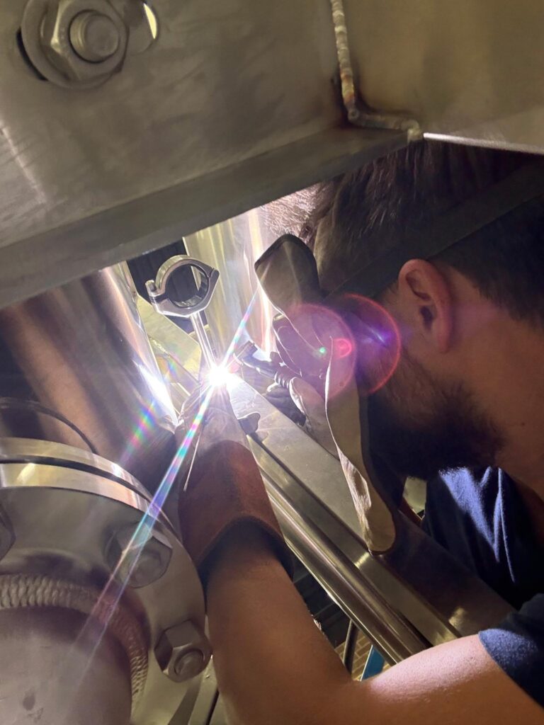
Day in the Life of a Welder

From Plans to Sparks, A Welder Brings Every Project to Life!
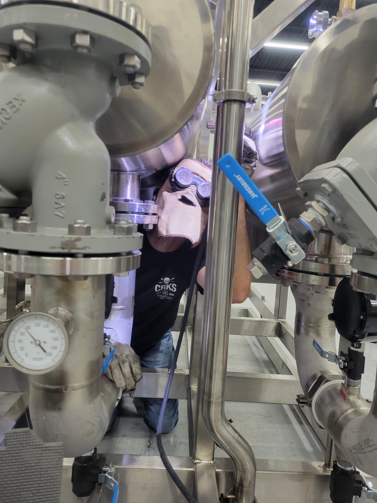
Take a look behind the scenes of a day in the life of Andrew Leblanc and Ben Fulp, our welders at M.G. Newell.
What is a typical day for welder Andrew Leblanc at M.G. Newell?

A typical day for a welder at MG Newell starts with coming into the shop, getting your bearings, and starting on the job you’ve been assigned to. Before you realize it, it’s time to refuel. Typically it could be Mexican, BBQ, or Subway for some of us. Then, it’s back to working on the job and tidying up before going home.

How long have you been a welder at M.G. Newell, and what education or background did you have to have to get this job?

I’ve been a welder at MG Newell for 7, almost 8 months, and graduated college with a diploma in welding. My background work ranged from welding at the Top Golf here in Greensboro to repairing excavator buckets, chandeliers, and more. 

What is your favorite thing about your job?

My favorite thing about my job is at the end of the day I’m still fairly clean and having meaningful relationships with my coworkers. 

If someone is interested in becoming a welder, what is one piece of advice you’d give them?

A piece of advice I would give someone interested in welding would be you can’t just be a good welder. It takes time, practice, and dedication. If you are willing to give it that, then your welding possibilities are endless. 

What is a typical day for welder Ben Fulp at M.G. Newell?

Honestly, there isn’t a typical day here at MG Newell. We have such a diversity of responsibilities and projects that nothing is ever typical. From handling raw materials, to shipping finished projects. We are the catch-all. 

How long have you been a welder at M.G. Newell, and what education or background did you have to have to get this job?

I’ve been associated with MG Newell since 2019 and have been in metalworking occupations since 2010. Working as a fitter, fabricator, welder, machinist, material handling, aerospace, and medical industry. I have a 2-year degree and continuing education over the years.

What is your favorite thing about your job?

I love the variety of tasks and challenges we encounter and the satisfaction of completing a project to its full aesthetic potential. Also attention to detail is key in this industry. 

If someone is interested in becoming a welder, what is one piece of advice you’d give them?

Pay attention to the “old timers.” They’re usually right. Absorb every ounce of knowledge you can. Bring your work ethic with you. Never be afraid to learn or TRY. People notice your effort and will “take you under their wing” if they see that you’re trying. Lastly, remember to have fun!

For more information, visit our website:  www.mgnewell.com and www.newellautomation.com.