Top Tips for COP

Top Tips to Make Your COP System Work For You – Part 2

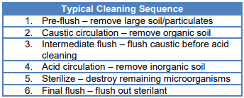
Out of Place But In Control

No matter how advanced and automated the CIP system is, there is always a need to clean the parts of production equipment not exposed to the cleaning process. There are pieces of equipment that simply cannot be cleaned where they are used, including piping, fittings, gaskets, valves or valve parts, filler parts and surfaces such as guides or shields, tank vents, tray pack, grinders, pumps, and product handling utensils such as knives. To properly clean and sanitize these units or parts, COP is employed to clean tear-down parts of processing and packaging equipment that require disassembly for proper cleaning. Because COP is essentially the systematic manual cleaning and sanitizing of production equipment that must be disassembled
in many cases, specific attention must be paid to cleaning underneath and around gaskets, O-rings, small pipes and other small surface cavities, gaps or other niches and harborage points in which potentially harmful residue and bacteria may accumulate. Cleaning knives or spoons that are used in a plant’s dishwasher would be considered a COP operation. In food plants, a common use of the COP cleaning method involves pieces of equipment that are small, complex and otherwise hard to clean. They are dissembled, rinsed and then cleaned and sanitized. COP may occur in a sink with a worker scrubbing to clean, or in tanks specially designed for COP. In these tanks, detergent and agitation are used to clean the equipment in question. Sanitizing may be done using hot water or chemical sanitizers. Small items, such as valves, sanitary fittings and such, can be placed in cages and cleaned with larger items. Options include doing a rinse, hot water wash with detergent, rinse and soak in sanitizer. Operators can also sanitize COP items by raising the second rinse temperature and holding for 15 minutes at >180F.

The basic steps in a COP operation include:

• Dry cleaning to remove dust, soil and other debris from the equipment to be cleaned and the area in which COP tasks will take place.

• A pre-rinse of the equipment and area on racks or in COP tanks.

• Soap and scrub the equipment and equipment components in COP tanks or vessels.

• Post-rinse parts to remove residual detergent or cleaning chemicals.

• Conduct pre-operational procedures and sanitize any equipment components that are not accessible once reassembled. Reassemble the equipment.

• Sanitize the reassembled equipment with a sanitizing agent or heat treatment.

Although the following tips for effective COP may seem obvious, they are well worth review:

Tip 1. Conduct COP tasks in order. It is important to understand that sanitation is a sequence of steps that build from the successful completion of the previous steps. In particular, COP practices, which involve multiple individuals working in the same area, multiple small parts to be cleaned and multiple sanitation steps for each item to be cleaned, are ineffective when steps are not taken in sequence. For example, it is not difficult to understand that the level of cross-contamination risk is raised if personnel are not all working at the same step at the same time. If one individual in that area is doing a final rinse while another person is doing a pre-rinse and the equipment is adjacent to each other, there is a risk of overspray from the unsanitized surface to the
sanitary one.

Tip 2. Consider using basket or tote washers. Another COP system that is of great value is comprised of basket or totes washers. Companies, such as those in the fresh-cut industry, who use a large number of small containers in their process operations, should look at these units. The container is simply loaded onto the system and it passes through the unit where it is rinsed, washed and rinsed. The cleaned containers should then be stacked so that they will not become re-contaminated. These washers may also be used for steel trays, pots or totes used in meat operations. A washer like this is usually much more effective than having an employee individually clean each and every tote, basket or pot. Tote washers, in particular, are usually designed to filter debris and reuse water, which can translate into reductions of water and chemical usage.

Tip 3. Use a tank rather than a rack. Parts removed for cleaning are either placed on a rack for cleaning or placed in a COP circulation tank and cleaned using a heated chemical solution and agitation. There are advantages to using a tank versus a rack, including:

• Parts may be cleaned all at once rather than individually which can be a time saver.

• The ideal vat or tank is stainless steel and sufficient size to fully submerge all parts, and will have smooth welds and no dead spots so that it will not be a source of contamination itself

• After dry cleaning major soil off the parts, they are placed in the tank and water is added to the tank that is either hot (125-130F) or will have steam injected to achieve that temperature.

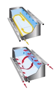
• Once the cleaning chemical is added, turbulence will be created, either from steam or mechanical means to aid in loosening soil.

When parts are clean, rinse thoroughly with clear potable water, inspect and sanitize. Parts may either be reassembled or stored on a rack until ready for use. One caution: Many COP operations are carried out by staff on production floors. They will literally work on the floor or on temporary tables. While the equipment and components may get clean, control is questionable.

Tip 4. Make sure the mechanical action tools used in COP tasks do not contribute to potential contamination. Since COP requires manual washing, or scrubbing, by staff for adequate soil removal and cleaning, the tools used take on critical significance. Make sure that cleaning brushes are rugged, made of non-absorbent material with bristles that are resistant to retaining soils and that dry quickly. Hand brushes and floor brushes should be color-coded to ensure that those designated for use on food contact surfaces are not used on non-food contact surfaces. The same goes for buckets, pails, utensils and other cleaning tools that are portable. These tools should undergo specific cleaning and sanitizing, as well, either with chemicals in a
dedicated wash-and-rinse sink unit or via heat treatment.

If you want more information, contact us by phone or email. 

Top Tips for CIP

Top Tips for CIP

Food processing equipment is either cleaned-in-place (CIP) or cleaned-out-of-place (COP). These cleaning methods offer processors an additional mechanism of process control in that each method CIP and COP systems enhance the ability of the sanitation crew to better clean and sanitize production equipment to a greater degree of food safety and quality assurance. CIP systems are extremely beneficial for aseptic and other processing operations in which interior surfaces of equipment such as tanks and pipes cannot be easily reached for cleaning, and COP methods are utilized for pieces of equipment and utensils that cannot be cleaned where they are used and must be disassembled, and for pieces of equipment that are complex and hard to clean. With a greater emphasis on sanitary design in food plants, equipment manufacturers and industry have worked together to make many improvements to equipment and parts that make cleaning and sanitizing more effective. Even so, plant sanitation crews and quality assurance/quality control (QA/QC) managers cannot rely solely on the fact that equipment is more cleanable today than in the past. Introducing or improving CIP and COP procedures, processes and systems in the food plant takes advantage of sanitary equipment design benefits, raising the level of assurance that when the production line starts up for a new run the process is in control from the get-go. With this in mind, here are a few tips to best-practice approaches in using CIP and COP systems to their fullest potential as process control measures.

Inside Cleaning 

CIP cleaning is utilized to clean the interior surfaces of pipelines and tanks of liquid and semi-liquid food and beverage processing equipment. This type of cleaning is generally done with large tanks, kettles or piping systems where there are smooth surfaces. CIP involves circulation of detergent through equipment by use of a spray ball or spray to create turbulence and thus remove soil. Chemical cleaning and sanitizing solution is circulated through a circuit of tanks and or lines to eliminate bacteria or chemical residues, which then flow back to a central reservoir so that the chemical solution can be reused. The system is run by computer, in a prescribed manner, to control the flow, mixing and diversion, temperature and time of the chemicals for cleaning and sanitizing. As with all cleaning methods, CIP systems utilize time, temperature and mechanical force to achieve maximum cleaning.

Automated CIP systems are most commonly used in processes in which liquid or flow-type material is being manufactured. This includes fluid products such as dairy, juice and beverages, as well as in operations using aseptic processing and packaging for low-acid or semi-fluid products such as liquid eggs, sauces, puddings, meal-replacement drinks, aseptic dairy and fruit, jam and marmalade, soups, ketchups and tomato-based products and salad dressings. Processors also are increasingly finding application for CIP systems in the manufacture of semi-solid foods, such as stews and spreadable cheese. A majority of food manufacturing operations producing these types of products today have installed CIP systems throughout the plant because they are efficient, cost effective and provide effective cleaning of cracks and crevices to reduce the formation of biofilms and growth niches where pathogens and other bacteria can survive. A major advantage of CIP is that it requires less labor since dissassembly, manual brushing or scrubbing, rinsing, reassembly and final sanitizing steps are not required. CIP systems also pose little risk to workers, if the system is properly maintained and operated. Due to automation of the method, CIP is very effective at containing chemical costs, lowering labor costs, minimizing repair and maintenance to equipment, and allowing the reuse of cleaning solutions.

In general, a CIP operation involves the following steps:
• Removal of any small equipment parts that must be manually cleaned, making sure that CIP and processing components are clearly segregated.

• Cool temperature water (<80F) is used to pre-rinse the equipment lines and piping to remove gross soil and to minimize coagulation of proteins.

• After the pre-rinse water is flushed from the lines, the appropriate cleaner solution or treatment is circulated for a requisite period of time to remove any soil, chemical or other residues. This step is followed by another water rinse.

• The final step is application of a sanitizing agent or method just prior to operation of the equipment. In aseptic operations, this step will be programmed into the system. Sanitizing can be with a chemical rinse or by the circulation of hot water. Hot water is used at high temperatures for CIP of equipment lines on which low-acid products are produced, and acidified water is used in those operations producing acidified or acid-containing products.

Before plant engineers can begin to design a CIP system for an operation, they have to be able to evaluate the manufacturer’s process thoroughly to determine what is going to work for each particular operation. Both the processor and suppliers need to understand the products being processed, the water chemistry involved and the operating parameters. There are several criteria the food processor should consider when installing, operating or improving upon existing CIP systems to assure that they are effective and in control:

Tip 1. Use vessels that are right for the process. 

The old adage, “You can’t sanitize a dirty surface,” applies to CIP processes and as such, vessels used should be of sanitary design. Tank sanitary design includes smooth and continuous welds, self-draining and internal surfaces that are round or tubular, not flat, with no ledges or recesses, to prevent accumulation of soil that cannot be 
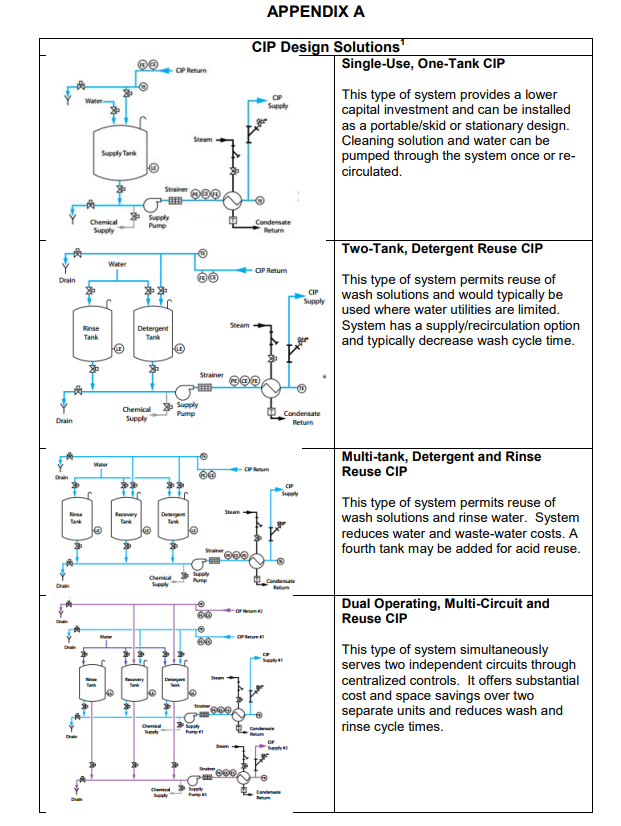
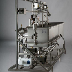
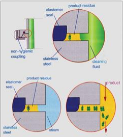
removed. It is important that tanks are properly vented, are self-draining and that the floor of the vessel allows for fast flushing. Figure 1 aptly illustrates the the contamination that can occur when equipment components such as coupling is not of sanitary design. If the only treatment materials that will be used in or flow through the system during CIP are rinse water and cleaning solution, a two-tank system will likely be adequate. If your process requires an additional function, such as an acid wash or retention of final rinse water, a three-tank or return pump system is warranted. Since CIP systems vary in application and sophistication, check with CIP equipment manufacturers to ensure that a system is right for your operation. Also make sure that there are a sufficient number of tanks for the cleaning solutions used and that they can contain sufficient quantity, about 50 percent more solution, than required to avoid running out of solution. Similarly, check that the spray balls used to deliver the cleaning agents to the interior surfaces of the equipment are actually appropriate for the tanks in which they are employed. Spray balls are designed to work within specified conditions and parameters involving flow rate, pressure and shape of the tank(s) in the circuit. If the spray balls are tampered with, damaged or not maintained in good condition, the distribution of the cleaning and sanitizing chemicals will be ineffective.

Tip 2. Identify and use the right cleaning chemicals and sanitizing solutions. 

It is essential that the right cleaner be employed in CIP systems. The chemical solution or treatment used in the CIP system must be capable of reaching all surfaces, and the surfaces are ideally made of stainless steel, not softer metals. It is
recommended that cleaning solution be changed approximately every 48 hours, where applicable.

Some common types of cleaners and sanitizers used in CIP systems include:
• Hypochlorites (potassium, sodium or calcium hypochlorite). These sanitzing agents are proven sanitizers for clean stainless steel food contact surfaces but the processor needs to maintain strict control of pH and concentration levels. Hypochlorites can be highly corrosive, and when improperly used, produces corrosive gas above 115F.

• Chlorine Gas. Like hypochlorites, chlorine gas is effective in CIP applications when used as a sanitizer for clean stainless food contact surfaces and requires tight pH and concentration control by the processor. It can also be highly corrosive to stainless steel, and when improperly used, produces corrosive gas above 115F.

• Peracetic Acid. Peracetic acid is a combination of hydrogen peroxide, acetic acid (vinegar) and a minute amount of stabilizer that form a strong oxidizing agent. These sanitizers are effective against all microorganisms, including spoilage organisms, pathogens and bacterial spores. Characterized by a strong odor such that you may want to use in well-ventilated areas, peracetic acid solutions are effective over a wide pH range and can be applied in cool or warm water in CIP systems or as sprays/washes in COP processes to all food contact surfaces in the plant.

• Chlorine Dioxide. If the production line is soiled with high organic loads, such as those found in poultry or fruit processing, chlorine dioxide is good to consider for use in the CIP system. This is because chlorine dioxide is effecive against all types of microorganisms even when organic matter is present on interior surfaces. However, preparation of this chemical should be automated because of its corrosiveness in acid solution.

• Acid Anionic (organic acids and anionic surfactant). The combination of an acid with surface-active agents produce a cleaning, rinsing and sanitizing solution that is ideal in CIP systems in which the removal or control of water hardness films or milkstone (such as in dairy processes) is critical. Acid-anionic surfactants are effective against most bacteria, and are odorless, relatively nontoxic and noncorrosive to stainless steel.

• Ozone. Approved by FDA for use on food contact surfaces, ozone-enriched water systems recirculate treated water through piping and equipment as a sanitizing treatment in CIP systems and processes. Ozone is also used in COP operations, applied as a direct ozonated water spray on food-contact and nonfood-contact surfaces, including equipment, walls, floors, drains, conveyors, tanks and other containers. Ozone-enriched water kills microbes as effectively as chlorine, and since it is generated on-site, its use eliminates the need for personnel to handle, mix and dispose of harsh chemicals for sanitation. Ozone readily reverts to oxygen, an end-product that leaves no residue on contact surfaces.

Tip 3. Use the correct flow rate.

For any CIP system to be effective, flow through the system must be at a high enough volume to assure that the flow is turbulent, since the turbulence is the mechanical action by which the interior surfaces of the equipment and piping is 
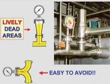
essentially “scrubbed.” This means the flow must be greater than 5 ft. per second. To achieve this flow rate, operators need to understand their specific processing system. To do this, make sure that pump sizes are sufficient for the size of the tank or length of pipes to be cleaned. The rule of thumb is that the pump can produce a flow rate four to five times the rate of the product flow. For example, turbulent flow may be achieved in a one-inch pipe at a flow rate of 24 gallons per minute (gpm), whereas a four-inch pipe requires a flow rate of 180 gpm. The same holds true for tanks, ovens or other large vessels. To calculate proper flow in a tank, take the circumference in feet times two. This will give the user a minimum flow in gpm needed to clean the tank and sufficient volumes of cleaner flowing down the sides of the tank for turbulent flow.

Tip 4. Don’t forget the connections.  

It is important that all connections in and to CIP systems are properly cleaned. As recommended in the 3-A Accepted Practices for Permanently Installed Sanitary Product Pipelines and Cleaning Systems, all connections between a cleaning solution circuit and product must have a complete physical separation or be separated by at least two automatic valves with a drainable opening (equal to the area of the largest pipeline opening) to atmosphere between the valves. It is a good idea to loosen line connections during the CIP process to allow for cleaning around the gasket. In addition, avoid creating dead-ends “or “lively dead areas,” which create difficult-to-clean sections of pipe (Figure 2), and ensure that the CIP system does not operate with parallel cleaning circuits or variable pipe diameters since both may reduce solution flow rates below 5 ft. per second. 

Tip 5. Monitor and verify. 

All too frequently, sanitation crew, managers and even process engineers rely too heavily on the fact that CIP systems or circuits are automated, believing that this automation translates into “automatic” process control. However, the only way to really know if the CIP system is working effectively is to monitor and validate the system’s components. Figure 3 shows why this is critical. In other words, although the CIP unit typically features a computer-controlled monitoring system, it is imperative that the mixing and metering of chemicals is monitored by routinely checking chemical concentrations, pH levels and monitoring pump and metering device performance. This can be accomplished by using rapid screening microbiological, chemical and environmental hygiene tests such as ATP bioluminescence swabs or devices near any openings to interior surfaces throughout the CIP cleaning shift. ATP can be used on exposed surfaces (fillers) or on rinse water to confirm the presence of organic material. These verification tests can also be applied to the CIP system connections such as gaskets, which should be checked regularly to verify the effectiveness of the cleaning program.

The water used in CIP processes must be continously monitored and verified. For example, monitoring and testing water chemistry is imperative because CIP spray balls may be compromised due to water hardness or turbidity. Hard water can precipitate on surfaces and clog holes, compromising flow and coverage. At the end of the day, if the water used in the cleaning process is not clean, the system cannot effectively clean (to a microbiological level) the equipment, pipes and tanks. Processors can and should do chemical tests on rinse water to ensure that residual cleaner and/or sanitizer is properly removed.

Similarly, water and cleaning solutions must be monitored for temperature to achieve process control. In CIP operations, the temperature of the solution is commonly measured, monitored and recorded via in-system computer controls. To verify that temperatures recorded are accurate, line personnel can use integrated software-driven data loggers and similar portable devices to randomly check solution temperatures during the CIP process.

If you want more information, contact us by phone or email. 

Safer Wash Down Stations – Case Study

Safer Wash Down Stations – Case Study

A snack company in Georgia uses steam-injected wash down stations in their plant.
For over 20 years, they have used these steam-heated water hoses to clean equipment, walls, floors, and ceilings in the plant, along with semi-CIP systems and adjacent high pressure hoses. Their biggest pain point with their current system was that the 
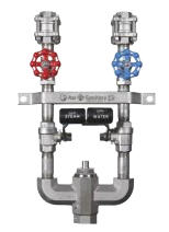
steam would bore out the inner working components in the washdown system. Safety had become an issue. The needle valves, once bored out, would not fall back into the saddle correctly. Once that occurred, a steam backdraft was created which would come out of the spray nozzle. These bursts of steam and extremely hot water were a huge safety risk for their associates. Casey O’Rear, our account manager in GA, listened to their concerns and decided to present the Ace Sanitary Silent Type Venturi Mixer (STVM) wash down station to the Safety Manager. The STVM uses a venturi mixing valve that combines steam and water for a constant stream at the operator’s set temperature. He brought in a sample that showed how easy it is to remove and replace the patented venturi cartridge and illustrated the safety shutoff feature if the water exceeds the factory set temp. 
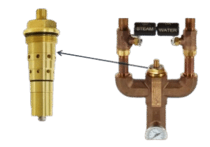
The Safety Manager was very impressed with the safety features inherent in the STVM washdown station. As an added bonus, he was also impressed with the ease of cleaning and switching out the cartridge. The existing washdown system had over 36 internal parts to replace. The STVM system has one cartridge to replace and change out only takes a wrench and a few minutes. The customer only needs to keep one extra cartridge on the shelf – a huge improvement to increase their uptime. Currently they have a trial unit on the wall and want to replace all of their old wash down units currently in the plant. Eliminating a safety issue and making maintenance easier – that’s how We Make It Work Better and how We Make It Work Safer!

If you want more information, contact us by phone or email. 

Cleaning bioreactors and fermenters with CIP systems

Cleaning Bioreactors and Fermenters with CIP Systems 

Early planning for the integration of clean-in-place systems for equipment cleaning is key.

By Chris McNulty
Pharmaceutical Technology
Volume 40, Issue 7, pg 46–48

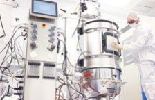
Manufacturing processes using bioreactors and fermenters require a well-thought-out plan to achieve a valid clean. A key consideration during the planning stage is how to successfully integrate an automated system for cleaning processing equipment in place without disassembly, also known as cleaning-in-place (CIP). Designing and sizing a CIP system for sufficient flow and pressure The flow and pressure required to CIP a manufacturing process, such as a bioreactor or fermenter, is dictated by the vessel spray devices and process lines. Static spray balls are the most common spray device used; however, some processes may use rotating impingement spray devices for heavier soil loads. Most standard bioreactor and fermenter designs include a spray device and piping connection package with recommended CIP supply flow rate and pressure requirements. Custom applications require an evaluation to determine spray device and piping design.
Spray devices. The flow and pressure required for static spray devices is determined by taking the circumference of
the vessel in feet and multiply it by three gallons per minute (gpm) per foot of circumference. For example, a threefoot diameter bioreactor would require a flow rate of 3 feet x π x 3 gpm to equal 28 gpm. This flow rate will yield
sufficient flow turbulence to clean the inside of the vessel. Most bioreactors have two to three spray devices to accommodate obstructions, such as agitator shafts and baffles, which cause shadows or areas that are not reached by a direct spray stream. Most spray balls require 25–30 psi to operate. The resulting flow rate from the vessel’s spray device calculation discussed previously is divided among the multiple spray balls, taking into consideration that each spray ball must receive 25–30 psi. If impingement-type spray devices are used instead of spray balls, the flow rate is commonly sized for 1.5 gpm per foot of circumference at 60 psi or greater. Multiple impingement spray devices are also needed to prevent shadowing.

Size of process piping. A bioreactor will have piping circuits of varying lengths and diameters to introduce gasses and ingredients to the process. Each of the piping paths will be proceeded by routing valves that need to be opened and closed during the CIP cycle. The flow rate needed to clean each of those paths is commonly based on achieving a velocity of five feet per second. The flow rate required to attain this is determined by the line diameter. For example, a one-inch line will require a flow rate of 10 gpm, whereas a 0.5-inch line will require only 2 gpm (see Table I). Table I: Pipeline flow rate (velocity) chart. As the routing valves are opened and closed, the flow rate through those different paths will change due to frictional loss and flow restrictions from items such as a sparger installed at the end of the line. To accommodate these fluctuations in flow, the CIP discharge pressure is increased or decreased to achieve the target flow rate. Another factor impacting pressure is the distance of the CIP system from the bioreactor. There will be a corresponding pressure drop related to the line size and elevation that must be accounted for in the sizing of the CIP supply pump. The pressure drop can be calculated using head loss tables for sanitary tubing and adding that pressure value to the pressure value needed at the bioreactor. Once the CIP solution is delivered to the bioreactor, it must be returned from the vessel outlet to the CIP system for recirculation or discharge to drain. It is necessary to incorporate a suitable return method in CIP planning, such as a sanitary liquid ring return pump or an educator, both of which are capable of evacuating water and air to avoid pooling in the vessel, which is detrimental to cleaning. The liquid ring pump may be located on the CIP skid or adjacent to the bioreactor while the educator is required to be located on the CIP skid. Both methods of return require a calculation of the return line head loss using the described method for the CIP supply line.

Utilities, space, and facility layout

When implementing a CIP system, one consideration is whether the process and location are best served by a portable or a stationary CIP system. Stationary CIP skids can be a one- or two-tank design. If speed of operation is important, a two-tank system with a separate solution and rinse tank will operate faster than a one-tank system. Portable CIP systems, while limited to one-tank designs, eliminate the need for permanent CIP supply and return piping by using flexible hoses. All CIP systems require one or two water sources. Generally, a lower grade water is used for the pre-rinse and chemical wash steps while a product quality water (i.e., deionized water or water for injection) is used for the final rinse. Water utility flow requirements typically range from 10 to 30 gpm at 25 psi, depending on the CIP skid design (some specialized designs are not restricted by this).

There are two common heating options available for CIP systems:
 Heat exchanger using plant steam. If only ambient water is available, or if there is a large surface area to heat, plant steam is used to provide indirect heating through a sanitary heat exchanger.
 Electric heater. If water can be brought into the system at 60 °C or higher, electric heating elements can be used to effectively elevate and maintain the heat. An electric heater is generally preferred for portable CIP systems to avoid the need for steam connections.

Regardless of design, 3-phase electrical power source (208/230/460 VAC) is needed to operate the system. A 30- to 100-amp service connection is typically required depending on the available voltage, heating method, and pump motor sizing.
A source of instrument air is needed to operate the air actuated devices located on the CIP skid. This includes valve actuators and air operated chemical pumps. An air source delivering 100 psi at 20 cubic feet per minute (CFM) is commonly specified. A suitable drain utility is also required, as drains need to be capable of handling 80 °C water at a flow rate equal to the highest CIP circuit flow rate (some specialized designs are not restricted by this)—and a pH range of 0 to 14. Quenching methods are available for drain systems using PVC drain piping, which is generally limited to a maximum temperature of 60 °C. Installations where a closed drain system is required, as opposed to a floor drain, require special consideration in the CIP system design to ensure the ability to drain and discharge into a line under pressure. While stationary systems only require these utilities to be local to the CIP skid, portable CIP  installations will need utilities at each point of use. Either system design may be located in a utility or grey space in contrast to a controlled environment. Should this be the case, a 0.2-micron hydrophobic vent filter should be installed on the CIP tank(s) to avoid potential contamination from the uncontrolled space during tank venting. Both stationary and portable designs need to allow sufficient space for clearances to meet maintenance and local code requirements. Special consideration should be given to long-term maintenance requirements where space must be available for elastomer and pump seal replacement, removal of heat exchangers or electrical elements, and for access to all valves and instruments. The room classification must also be considered during CIP design. If the CIP system will be in a wash-down area, the electrical controls should be designed for a NEMA 4X location. Hazardous locations, such as Class I, DIV 1, require specialized electrical components and a purging system for the panel in order to meet the safety requirements. Finally, most bioreactor control systems require a means of communication with the CIP skid to signal valve cycling, agitator operation, alarm conditions, and cycle completion. The automation method to accomplish this may be provided through discrete low-voltage signals or through an Ethernet connection. In either case, it is important to determine these requirements early in the project to make sure they are understood.

Optimizing cycle times

Optimizing cycle times increases system productivity by minimizing the time and utilities needed to rinse and wash  the process equipment. A system’s cleaning cycle parameters for a process are first developed based on the initial coupon studies performed, which provide parameters for TACT (Time, Action, Chemical, Temperature). These parameters can be optimized in the field during the commissioning process. During the commissioning, the team should test the cleaning recipe steps to identify the optimum times, chemical concentrations, and temperatures (note: flow rate and pressure are dictated by the process design as previously described and therefore not changed). For example, the pre-rinse is used to remove a bulk of the soil load. If the prerinse is initially set for five minutes, but the return fluid is coming back to the system clear after two minutes, the cycle should be set for two minutes and retested to confirm this is a repeatable condition. This same method of testing can be extended to the chemical wash steps, where an increase in temperature may be evaluated to reduce chemical usage and reduce cycle time. CIP return and air-blow step times should be evaluated to ensure they are effective. If there are several different products running through a process, the goal is to optimize the cycles down to the minimum time required to clean the equipment following each product that runs through the process. So, it is not ideal to run a universal program set for the hardest-to-clean product, which will unnecessarily extend cycle times and result in excessive chemical and water use. An optimization option for multiple products being run through a process is to set a series of recipes such as long, medium, and short cycles to clean categories of products. It is important to plan for optimization in the project schedule prior to validation. Making changes to the process after the CIP system is validated is costly and will prove difficult to accomplish.

If you want more information, contact us by phone or email. 

CIP and COP Overview

CIP and COP Overview

Sanitary equipment design is defined as the engineered design of handling, processing, storage facilities and equipment to create a sanitary processing environment in which to produce pure, uncontaminated, high-quality products consistently,
reliably and economically. The universal guideline that is most useful to the food industry in this regard is Good Manufacturing Practices (21 CFR Part 110), Sec. 110.40, Equipment and utensils, which reads:

(a) All plant equipment and utensils shall be:
• adequately cleanable
• preclude adulteration with lubricants, fuel, metal fragments, contaminated water, or any other contaminants
• installed and maintained as to facilitate the cleaning
• corrosion-resistant when in contact with food
• made of nontoxic materials and designed to withstand the environment of their intended use

(b) Seams on food-contact surfaces shall be smoothly bonded or maintained so as to minimize accumulation of food particles,
dirt, and organic matter and thus minimize the opportunity for growth of microorganisms.

(c) Equipment that is in the manufacturing or food handling area and that does not come into contact with food shall be so
constructed that it can be kept in a clean condition.

To meet these and other cleaning standards, Clean-In-Place (CIP) and Clean-Out-Of-Place (COP) systems are used. CIP and COP can be engineered to meet any industry standard including 3A, PMO, USDA and AMI.

Clean-In-Place (CIP)
CIP is a method of cleaning the interior surfaces of pipes, vessels, filters and other processing equipment without disassembly. The benefit is that the cleaning is faster, less labor intensive and more repeatable  while also posing less risk to chemical exposure of workers. The cleaning cycle is comprised of different stages with water and/or cleaning solutions that require a certain time, temperature, flow, velocity and detergent concentration to achieve the necessary results.
The challenge is that to remove soils, CIP solutions must reach the surface and soil to have an effect.
CIP systems can be designed as a single-use CIP or re-use CIP. While single-use CIP has a lower initial investment, long-term cost is higher as chemicals are dumped after each cycle. Cycle time is also typically longer with single-use system as time is needed to do water fills and heat the water. Re-use CIP systems recover ~80% of the chemical and water volume. Utility costs can also be realized by saving heated solutions. Several design options are shown in Appendix A. Flow of liquid is responsible for carrying both hot water and cleaning solution to the soil on a surface and also for providing the physical mechanism of lifting and carrying the soil away. Studying the flow conditions during CIP can help insure the system is meeting cleaning requirements. Depending on soil load and the process layout, CIP design is typically one of
the following:
 Deliver highly turbulent, high flow-rate solutions (i.e. piping and some equipment)
 Deliver solution as a low-energy spray to fully wet the surface (lightly soiled vessels with static sprayball)
 Deliver solution through a high-energy impinging spray (highly soiled or large diameter vessels with dynamic spray)

When evaluating a new CIP system (or an upgrade to your existing system), consider a few basic design requirements:
 The flow rate to clean vertical tanks with fixed spray balls is 2.5-3 gpm x tank circumference
 The flow rate to clean horizontal tanks with fixed spray balls is 0.25 gpm x surface area (sq.ft.)
 Add additional flow devices for agitators, baffles, etc.
 The effective spray distance is ~8 feet radius.
 Increase spray ball flow rate to clean outlet piping at 5 ft/second if required.
 Minimum CIP supply pressure required is 15 psi.

Clean-Out-Of-Place (COP)
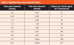
COP systems are used to clean equipment parts and components. They provide consistent, repeatable cleaning with reduced chemical and water usage, less labor and faster cleaning than hand washing. COP is typically used for pump rotors, impellers, cases, hoses, tubing, fittings, gaskets and any other handling equipment. COP washers can be designed as portable/skid or stationary systems with single or multiple compartments. Standard models are typically built with a 304L stainless steel construction with jet manifolds and a centrifugal pump to pump the water and cleaning solution through the system. Designs can be further upgraded to 316L stainless and can include a heat exchanger and PLC controls for semi-automation of sensors and feed systems.

When sizing and specifying a COP system, one should consider:

 Industy/Application – finish level, control and recording needed
 Product soil type and condition – baked on, loose, wet, etc
 Largest component(s) that must be washed – loading and spacing
 Type and configuration of components – tubing, machine parts, etc
 Batch size – quantity of items and turnaround time available
 Utilities available
 Location in your facility – space limitations, portable or fixed

One final consideration with COP systems are the jet manifold options. Spray jets can be mounted as side jets or end jets. With end jets, a pump forces the cleaning solution from one end to create a counter-current lengthwise circulation. This type of circulation would be recommended for tubing and hoses to clean the inner diameter. Side jets are mounted around the outside of the tank; pointing up and down to create a rolling turbulence. For deeper tanks (>24”), a second manifold is added to each side to create a quad-jet manifold. Combination washers can be designed to include both side and end jets. In this system, butterfly valves allow the operator to switch between the two circulation systems.

If you want more information, contact us by phone or email.