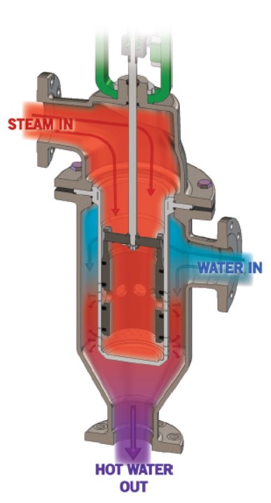
Magnetic Flowmeters 101

Flowmeters 101 

Magnetic Flowmeters – How They Work 

Flowmeters play a vital role in sanitary processing.  They are used to measure incoming raw materials, incoming water supply, CIP solutions, ingredients in your formulation, final product production and even waste water leaving the plant.  Considering their use in critical applications, ensuring that you are using the right type of meter with the correct level of accuracy for your application can be the difference in the quality of your product and save you thousands of dollars in lost revenue or profit.

Magnetic Flowmeters

Magnetic flowmeters (or mag meters) use Faraday’s Law of Electromagnetic Induction to determine the flow of liquid through a pipe.  This type of flowmeter works by generating a magnetic field and channeling that through the liquid in the pipe.  Faraday’s Law states that flow of a conductive liquid through the magnetic field can cause a voltage signal that electrodes are sensing on the tube walls.   When the fluid is moving faster, more voltage is generating.  The voltage generated is proportional to the movement of the liquid.  Transmitters process the voltage signal to determine liquid flow.
The signals produced by the voltage are linear with the flow.  With this, the turndown ratio is very good without sacrificing accuracy.

Pros and Cons

Since these flowmeters measure conductivity, obviously the fluids measured need to be conductive – water, acids and bases.   Low conductive liquids, such as deionized water or gases, can cause the flowmeter to turn off and/or measure zero flow.  There is no obstruction in the path of the liquid, therefore no induced pressure drop across the meter.  One other benefit of mag meters is that they are able to use gravity-fed liquids.  With gravity-fed liquids, the flowmeter orientation is vertical so that the flowmeter is completely filled with liquid.  These flow meters are sensitive to air bubbles because the meter cannot distinguish entrapped air from the liquid.  Air bubbles will cause the meter to read high.

We choose mag meters because they have no obstructions, are cost-effective and provide highly accurate volumetric flow.  Additionally, they can handle flow in either direction and are effective at low and high volume rates.

Graco EODD Pump

A Massive Leap Forward in EODD Pump Technology

GRACO EODD PUMP
  • Quieter operation and smaller footprint enable easier installation and service—the design can pay for itself in energy savings in under a year
  • Efficient, affordable drop-in replacement to reduce energy costs up to 80% being competitively priced vs. AODD pump technologies
  • Only electric diaphragm pump that stalls under pressure, eliminating the need for pressure sensors and additional controls to prevent pump failures and reduce downtime
  • Integrated I/O allows for remote operation and speed control to minimize operator oversight
  • Smart control technology adjusts pump speed to aid in priming or prevent dry running cavitation that damages pumps
  • Plug-and-play installation for fast, easy and affordable transfer operations upgrades
  • Delivers clear advantages over other pumps, including centrifugal, lobe, gear, progressive, peristaltic and piston/ plunger technologies
Other Electric Pumps

• Are expensive
• Require a VFD
• Have flow and pressure limitations
• Are not as efficient as QUANTM
• Have a large footprint

QUANTM – Graco EODD Pumps 

Use up to 8X less energy than AODD 

The Economic Case for Energy Savings & Sustainability

• Consumers are purchasing from suppliers that show a real commitment to sustainability.
• Investors are more selective than ever about what brands they support, often based on factors like their sustainability and corporate social responsibility initiatives.
• Regulators provide a bevy of incentives like tax credits to manufacturers in exchange for sustainability bona fides, like reduced energy consumption and carbon emissions.
• Governments are investing significantly in solutions that help them meet global sustainability benchmarks

  • Talk to your energy provider.
  • Determine how much compressed air is costing you.
  • Find out what incentives you qualify for.
  • Decreased energy use.
  • Less use of compressed air.
  • Quick installation for less downtime.
  • Less specialized training & manpower required.
  • Up to 80% less energy use than AODD.
  • Plug-and-play into any 110V-240V outlet.
  • Initial Cost Comparable with AODD.
  • ROI: 1 year.
  • Establish baselines. Know how much energy you use today,
    even if it’s just a ballpark.
  • Invest in efficient equipment and practices. From pumps to
    lighting, the electric technologies outlined in this e-book are
    great places to start outfitting your facility for the sustainability focused future.
  • Collect and interpret data. If you’re replacing equipment, know how much energy and money it’s saving you. It’ll show you where your investments are having the most impact and identify more areas of opportunity.
  • Set specific goals. Once you start saving, don’t rest on your laurels. Using the information you collect, set milestones for your company to hit next, like kWh caps and recycling volume.

The recent development of our electric-operated double diaphragm (EODD) pump allows us to bring cost-saving ideas to manufacturers of all sizes.

Electropolishing vs. Passivation

Electropolishing vs. Passivation

Addressing Common Misconceptions 

One of the most frequently asked questions online, “Which is better, passivation or electropolishing?” is driven by a misunderstanding of the two processes and the different roles they play. In fact, the two processes are frequently complementary and doing one without the other can result in an unreliable system requiring constant maintenance.

For some applications, treating stainless steel with both electropolishing and passivation may be necessary to maximize the metal’s resistance to corrosion and meet specific standards. Two major industry standards with stringent surface chemistry requirements that may necessitate both treatments are: SEMI (Semiconductor Equipment and Materials International) standard, which is widely used in the semiconductor and electronics manufacturing industries.

What is Electropolishing? Superior Finish and Performance

What is Passivation? Enhancing Corrosion Resistance

Identifying and Addressing Contamination or Corrosion

Electropolishing utilizes a combination of electricity and chemistry to smooth the metal’s surface by removing the metal from the peaks of any raised surfaces on a microscopic level.

The metal removal rate is controlled by the electrical settings of the electropolishing equipment, the process is repeatable for a given alloy, electrolyte concentration and conductivity, and current density combination.

A well-electropolished surface significantly reduces locations where contamination can become caught on the surface and become a point where corrosion will flourish.

Passivation, on the other hand, is a chemical treatment to enhance stainless steel’s natural passive layer which protects the underlying metal from corrosion.

The passivation chemistry removes free iron or other metallic impurities on the surface which would become a source of corrosion.

The result is a contaminant-free, chromium-rich oxide layer that is chemically inactive, or “passive.”

Early warning signs of contamination or corrosion are typically found during the regular quality control sampling and inspection of a system and, depending on the situation, can be addressed by remediation, cleaning and a passivation treatment.

However, in situations where the symptoms are missed, or not addressed, both metallic and biologic surface contamination can result in accelerated corrosion through the underlying metal. In the most serious cases, the part fails and will have to be replaced. It goes without saying that any product that has passed through this system risks being seriously compromised.

Even if the situation is caught before failure, the pitting that occurs due to corrosion will need to be repaired. This will involve mechanical polishing, followed by electropolishing and then passivation of the affected area to bring it up to the same level of protection and cleanliness as the rest of the system.

Routine Maintenance and Preventative Measures

In most cases, electropolishing will need to be performed only once and then passivated as part of commissioning a system. The result is a smooth surface, meeting the surface roughness requirement of the system, presenting fewer opportunities for internal corrosion or contamination to spread through the system to other locations, or into the product itself.

By including passivation as part of a maintenance plan, plant owners can be proactive in preventing corrosion or other contamination buildup. This decreases the likelihood of
unscheduled remediation services and aids in the longevity of the system itself.

Cabinet Washers

Reliable, Consistent Cleaning for your COP parts

Food and beverage manufacturers have a significant number of parts that need to be cleaned daily; each with specific needs due to varying soil levels, manufacturing processes and soil properties. And, of course, everything needs to be cleaned quickly to keep production moving. That is where cabinet washers come into play.

Sani-Matic Cabinet-Washers

The automated Sani-Matic cabinet washers design and manufacture purpose is to address these challenges efficiently and effectively, while lowering long-term operating expenses.

Therefore each cabinet washer comes with an exclusively-designed sanitary spray assemblies that distribute cleaning solution evenly throughout the washer.

The cabinet washer’s spray arms and oscillating high-impact manifolds effectively remove difficult residues from interior and exterior product contact surfaces, while the PLC controls the cleaning cycle to ensure a repeatable and documentable process.

A complete clean, every time! That’s Cleaning Confidence!

Easy-to-Specify

The SaniCab P Series Configured Design Offering is model key driven and accompanied by a detailed Technical Datasheet for easy specification. Also if your process requires a system outside of the pre-engineering offering, Alternative Design Requests are met with a custom-engineered solution.

Sanitary Racks Designed and Optimized for Your Process

Each food and beverage manufacturer has different process soils to remove and parts to clean.

Sani-Matic’s engineers have designed Standard Racks for common clean-out-of-place process parts such as scale buckets or weigh hoppers, 3- and 5-gallon buckets, pallets, totes, trays, and buggies.

However, they also design Custom Racks following three design tiers: Customization – Standard Rack, Custom Rack, and Custom Active Rack.

The details for the General, Standard, and Custom Racks will be in the SaniCab P Series Technical Datasheet.

Why Sani-Matic Racks and Transfer Carts?

  • More Clean with One Machine. With multiple racks, operators can clean diverse process parts with one capital equipment investment.
  • Efficient. Racks design is for optimized load capacity and intuitive part placement.
  • Safe Transport. Transfer carts assist operators with easy and safe process part handling.
  • Sanitary Design. The transfer cart has an open channel design to prevent harboring bacteria. It remains outside of the washer to prevent the floor’s bacteria from entering the washer.

The Scale Bucket-Piston Filler-Tray-Pallet-Bucket-Barrel-Hose-and More Washer

The Sani-Matic SaniCab P Series is an automated, versatile cabinet washer designed to improve food and beverage processors’ productivity and cleaning results for a wide variety of product contact items. These items include scale buckets or weigh hoppers, totes, barrels, piston fillers, trays, buckets, hoses, buggies, and more.

Increased Productivity and Repeatable Cleaning Results

Food and beverage manufacturers face ongoing pressure to increase productivity while also meeting the sanitation preventive controls demands of FSMA and HACCP. With SaniCabs cabinet washer’s cleaning cycles as short as 10 minutes, and therefore racks designed to optimize productivity, a sanitary design, and documentation capabilities, manufacturers can achieve both.

VFD Terminology

A VFD is a device that controls the speed of an electrical motor by varying the frequency and voltage of its power supply. The VFD also has ramp-up and ramp-down capabilities to start and stop the electrical motor smoothly.

Here some reasons why we need to control the speed of an electrical motor.

  • Save energy and improve system efficiency.
  • Reach the desired torque or power for the process requirements.
  • Lower the noise levels of pumps, blowers, fans, compressors, etc.
  • Reduce mechanical stress on the machines and improve their life cycle.
  • Improve the working environment.

3 Primary Sections

A VFD consists of 3 primary sections:  the rectifier/converter, the DC Bus, and the inverter.

The rectifier/converter is the first of the three sections of a VFD’s main power circuit. First in terms of power flow. Incoming AC line voltage is rectified or converted to DC voltage in the converter section. Which consists of diodes, silicon-controlled rectifiers (SCRs), or insulated gate bipolar transistors (IGBTs) connected in a full-wave bridge configuration.  One rectifier will allow power to pass through only when the voltage is positive. And then a second rectifier will allow power to pass through only when the voltage is negative. You will use two rectifiers for each phase of power.

The DC Bus is the 2nd section of a VFDs main power circuit.  The main function of this link is to store, smooth and deliver the DC voltage.  The incoming power from the rectifier contains voltage ripples which smooths out using capacitors.

The 3rd section of a VFD power circuit is the Inverter.  The inverter section of a VFD is the primary difference between an AC drive and a DC driver.  This section is comprised of Insulated Gate Bipolar Transistors (IGBTs). Which convert the DC voltage back into AC voltage to feed the motor.  IGBTs are very fast and very small semiconductor switches that are actuated electronically, so that creates a sinusoidal output current.

A microprocessor unit controls all three of them. It performs numerous functions such as controlling the speed, monitoring the alarms and faults and interfacing the AC drive with different devices using a communication protocol.  This means that the user can now control the start/stop function, motor speed control and receive feedback about current speed and other motor or device variables.

Nuvonic

PureLine D
Also available in our Food & Beverage product range…
PureLine DC+DCD
Dechlorination and Chlorine Dioxide removal
PureLine DO
Ozone removal and treatment 
PureLine PQ 
3rd party bioassayed systems for critical treatment or as a pathogen barrier 
PureLine S 
Sugar syrup treatment

UV TREATMENT FOR FOOD AND BEVERAGE

Our PureLine D PH systems are aimed specifically at providing UV treatment for product and process waters used in the food and beverage industry.

By using a UV system you will eliminate harmful micro-organisms, reduce the bio-burden, protect against bio-fouling, lead to fewer CIP/SIP cycles and lower operating costs. Each system comes with a UV sensor to measure the active output of the UV system and make it easy to monitor and log performance. 

Potential Locations of the PureLine D PH™

Key Features

Intelligence 

  • UV intensity sensor measuring active wavelengths.

Optimization 

  • UV Water treatment.
  • Designed for the food and beverage industry. 

Integration 

  • Compact Design 
Benefits For You

Intelligence

  • Easy to monitor and log system performance. 

Optimization 

  • Does not affect taste and color of final product
  • No chemicals.
  • Industry compliant materials.
  • Sanitary Design.
  • Self-Cleaning.

Integration 

  • Easy integration.
What It Gives You

Intelligence 

  • Continuous verification of performance with in-built low intensity alarm.

Optimization

  • Protect your process waters from microbiological contamination including chlorine resistant Cryptosporidium and Giardia.
  •  FDA-approved materials used for all wetted parts.
  • Chamber with tri-clamp connections and < 0.38 µm internal finish.
  • *Automatic wiper (quartz cleaning).

Integration 

  • Can be fitted to skids.
  • Can be retrofitted to existing process.

Coriolis Flowmeter 101


Flowmeters play a vital role in sanitary processing. They are used to measure incoming raw materials, incoming water supply, CIP solutions, ingredients in your formulation, final product production and even waste water leaving the plant.
Considering their use in critical applications, ensuring that you are using the right type of meter with the correct level of accuracy for your application can be the difference in the quality of your product and save you thousands of dollars in lost revenue or profit. In sanitary processing, one will typically find mechanical flowmeters (Positive Displacement, Turbine), electromagnetic and Coriolis flowmeters.

Coriolis Mass Flowmeter


The effect of a merry-go-round on balance is achieved through flowmeters with a split coil design, which measure the time delay between two sine waves, directly proportional to mass flow rate.

PROS
  • Used in critical and challenging applications.
  • Handles low to high flow rates with high accuracy.
  • Reliable, minimal calibration requirements, low maintenance costs.
  • Fluid density doesn’t impact flow measurement.

A Coriolis mass flowmeter operates on motion mechanics principles, using a vibrating tube to measure fluid flow. As fluid moves through, it accelerates towards peak amplitude vibration, while decelerating fluid moves away, causing a twisting reaction.


CONS
  • Higher initial cost than other flowmeters.
  • Considers pressure drop, especially for high viscosity fluids.

ExiFlo

Major Impact
  • Does not require disconnection and invasive inspection.
  • Able to be installed retrospectively to existing lines with different types of heat exchangers or tanks.
  • Utilizes process water, resulting in no contamination or post-test cleaning.
  • Qualification of leaks.
Medium Impact
  • On demand testing carried out on an automated or manual process at start of each shift or batch.
  • Tests are carried out in-situ and under operational conditions without requiring a high-pressure differential.
  • Data available in real time remotely or at the module.
  • Automated operation with no advanced training required.
Additional Impact
  • Significantly shorter and reliable testing eliminating downtime.
  • Mitigates false readings due to liquid test media.
  • More accurate pressure testing tolerance.

ExiFlo is an innovative retrofit hardware device which monitors and tests the integrity of any close liquid or gas system in service within heat exchange systems. ExiFlo is able to identify leaks across the boundaries and into the outside environment without the need to take the system off-line. Furthermore, these tests are quickly carried out before and after each production cycle, to ensure that each product batch receives a pass or fail certification before leaving for distribution.

ExiFlo minimises risk of contamination from cross-channel flow, which can lead to unplanned and costly downtime, reduction in efficiency, contamination of utility systems and product recalls that are highly damaging to brand reputation. In this manner, ExiFlo maximises your brand’s compliance.

Click to Watch A Video for More Information

Compound Planetary Inline Spiral Bevel (SBT)

Compound Planetary Inline Spiral Bevel (SBT) gearmotors combine our Inline Planetary (IL) and Spiral Bevel (SB) gear reducers to offer a greater variety of speed reduction than either gearbox alone. Compact and highly efficient, SBT gear motors are ideal for high ratio, high power applications

Compact and highly efficient. The IL gear reducer mounts directly off the motor shaft. The IL shaft then feeds into the SB gear reducer housed in a unique tubular casing. The tubular housing features smooth, easily cleanable surfaces. (SBT) gearmotor with a 5HP HAZARDOUS LOCATION (XP) Our patented Hazardous Duty/Explosion Proof (XP) motors are ideally suited for processing applications requiring strict sanitation and washdown tolerance in combination with safety concerns arising from hazardous liquids, vapors and or dust.


Special Features

• Sanifan Technology

• Positive Pressure Lubrication System

• Compact Design

• Solid or Hollow-Bore Shafts

• Vertical or Horizontal Orientation

• Output Shaft at Right Angle to Input Shaft

• O-Ring Sealed Sanitary Shaft Cover

When To Use

• High efficiency, quiet operation,
  right angle drive, low overhead room

• Available Output RPM: 9 through 200

• Available Power: 5 HP through 40 HP

Combining our Sanifan Technology motor, an IL series planetary reducer, and spiral bevel final output stage yields an exceptionally sanitary and efficient package. The SBT tubular housing features smooth, easily cleanable surfaces and can be supplied as flange mounted, face mounted or foot mounted. Large bore hollow shafts are easily accommodated, making these ideal for “piggyback” scraper/agitator mixer drives. An internal oil pump assures proper bearing lubrication in any orientation, at any speed. The pump is bi-directional, meaning proper performance is assured regardless of output rotation direction and is maintenance free.

These units make excellent retrofit candidates for existing unsanitary cast iron gearmotor drives and SMI engineers will partner with you to ensure a “drop on” retrofit success.

The IL gear reducer mounts directly off of the motor shaft. The IL shaft then feeds into the SB gear reducer housed in a unique tubular casing. The tubular housing features smooth, easily cleanable surfaces and is often equipped with a flange or C-face mounting.

The SBT output shaft is at right angle to the motor shaft and is available as solid or hollow bore with either a vertical or horizontal orientation. SBT units are made to order allowing OEMs and end users to specify a particular mounting configuration for the best possible integration with new or existing equipment.

SPX Flow Preventative Maintenance Checklist

Implementation of preventive maintenance plan keeps SPX FLOW products running at optimal levels and protects your product investment. Use the below checklist to figure out when it is time for regular product inspections and part replacements using SPX Flow products spares to extend your products lifecycle. 

Oil/Lubrication

Check for damaged rear oil

Possible Causes

  • Seal may be old and worn
  • No grease on lips to lubricate
  • Shaft worn under seals
  • Not centered on shaft when installed 

Possible Solutions 

  • Replace seals 
  • Properly lubricate with grease when installing 
  • Inspect shaft surface under seals 

MAINTENANCE FREQUENCY: EVERY 3 MONTHS

Check for Leaks-Flush fluid

Possible Causes

  • Damaged seal, fitting or flush tube
  • Damaged flush-side seal components, damaged elastomers

Possible Solutions 

  • Replace seal, fitting or flush tube 
  • Replace flush-side seal components 
  • Replace elastomers 

MAINTENANCE FREQUENCY: WEEKLY 

Check Front Grease Seals

Possible Causes

  • Seal may be deteriorated or worn
  • Shaft worn under seals, or no grease on lips to lubricate

Possible Solutions 

  • Replace seals 
  • Properly lubricate with grease when installing 
  • Inspect shaft surface under seals 

MAINTENANCE FREQUENCY: EVERY 3 MONTHS 

Check for Leaks Product

Possible Causes

  • Damaged seals or elastomers

Possible Solutions 

  • Replace seals or elastomers 

MAINTENANCE FREQUENCY: WEEKLY

Check oil level, for contaminants and for leaks (if applicable)

Possible Causes

  • Oil leak from gear case cover, oil seal or gear case rear oil seal
  • Loose back cover, Oil plug damaged

Possible Solutions 

  • Replace oil seals 
  • Check or replace oil plug 

MAINTENANCE FREQUENCY: WEEKLY

Check for excess grease in clean-out plugs

Possible Causes

  • Excess grease accumulates with normal operation

Possible Solutions 

  • Remove excess grease from clean-out plugs 

MAINTENANCE FREQUENCY: MONTHLY

Check for sharp edged shaft shoulder

Possible Causes

  • Loose rotor nut(s)
  • Belleville-style washer(s) on backwards
  • Rotors slammed against shoulder when installed
  • Backface clearances not even

Possible Solutions 

  • Torque rotor nut(s) properly
  • Install Belleville-style washer(s) correctly
  • Remove sharp edge with file to prevent cutting shaft o-ring
  • Verify backface clearances are even

MAINTENANCE FREQUENCY: EVERY 3 MONTHS 

Check for worn rotor hub end or shaft shoulder

Possible Causes

  • Loose rotor nut(s)
  • Belleville-style washer(s) on backwards
  • Rotors slammed against shoulder when installed

Possible Solutions 

  • Torque rotor nut(s)
  • Install Belleville-style washer(s) correctly
  • Replace rotors and shafts or shim front bearing(s) to maintain proper backface clearances

MAINTENANCE FREQUENCY: EVERY 3 MONTHS 

Check for worn/damaged rotor or shaft keyway(s) or key(s)

Possible Causes

  • Loose rotor nut(s)
  • Belleville-style washer(s) on backwards

Possible Solutions 

  • Replace rotors, shafts and keys
  • Torque rotor nut(s)
  • Install Belleville-style washer(s) correctly

MAINTENANCE FREQUENCY: EVERY 3 MONTHS 

Check for rotor tip to rotor tip contact or uneven rotor tip to rotor tip clearance

Possible Causes

  • Hard object jammed into rotors and twisted shafts

Possible Solutions 

  • Replace shafts 
  • Install strainers if necessary 
  • Check and replace gears if necessary 

MAINTENANCE FREQUENCY: EVERY 3 MONTHS 

Check for rotor tip to rotor hub contact

Possible Causes

  • Loose rotor nut(s)
  • Belleville-style washer(s) on backwards
  • Back face clearances not even
  • Bearings need replacing

Possible Solutions 

  • Torque rotor nut(s) properly
  • Install Belleville-style washer(s) correctly
  • Verify backface clearances are even
  • Check and replace bearings

MAINTENANCE FREQUENCY: EVERY 3 MONTHS 

Inspect for Gear backlash

Possible Causes

  • Lack of lubrication
  • Excessive hydraulic loads
  • Loose gear locknuts

Possible Solutions 

  • Check lubrication level and frequency
  • Reduce hydraulic loads
  • Torque locknuts to specified torque valves
  • Check and replace gears if necessary

MAINTENANCE FREQUENCY: EVERY 3 MONTHS 

Inspect bearings, axially or radially movement

Possible Causes

  • Lack of lubrication
  • Excessive hydraulic loads
  • Product of water contamination

Possible Solutions 

  • Check lubrication level and frequency
  • Reduce hydraulic loads
  • Ensure no excess grease build-up
  • Replace bearings If necessary

MAINTENANCE FREQUENCY: EVERY 3 MONTHS 

Inspect gears for worn or broken teeth

Possible Causes

  • Lack of lubrication
  • Excessive hydraulic loads
  • Loose gear locknuts

Possible Solutions 

  • Check lubrication level and frequency
  • Reduce hydraulic loads
  • Torque lockouts to specified torque valves
  • Check and replace gears if necessary

MAINTENANCE FREQUENCY: EVERY 3 MONTHS 

Inspect for loose gears

Possible Causes

  • Gear locknuts not tongued properly
  • Locking assembly not torqued properly
  • Worn gear key

Possible Solutions 

  • Torque gear nut to specified toque value
  • Check and replace gears if necessary
  • Inspect gear keys, shaft keyway and shaft, replace If necessary

MAINTENANCE FREQUENCY: EVERY 3 MONTHS 

Pump Remanufacture Program 

The Remanufacture Program will restore your Universal series pumps* to new pump status as many times as possible. Regardless of condition, pumps will be remanufactured TWICE GUARANTEED.

Factory Warranty 

You get a NEW Full-Year Warranty along with the same quality, performance-tested, rugged reliability you’ve come to expect from Waukesha Cherry-Burrell.

Pump Exchange 

Our convenient Pump Exchange Policy allows you to receive your newly remanufactured pump prior to returning your worn unit resulting in NO DOWNTIME.