PureLine D
Also available in our Food & Beverage product range…
PureLine DC+DCD
Dechlorination and Chlorine Dioxide removal
PureLine DO
Ozone removal and treatment
PureLine PQ
3rd party bioassayed systems for critical treatment or as a pathogen barrier
PureLine S
Sugar syrup treatment
UV TREATMENT FOR FOOD AND BEVERAGE
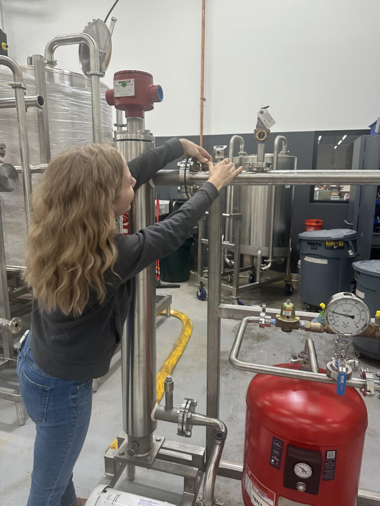
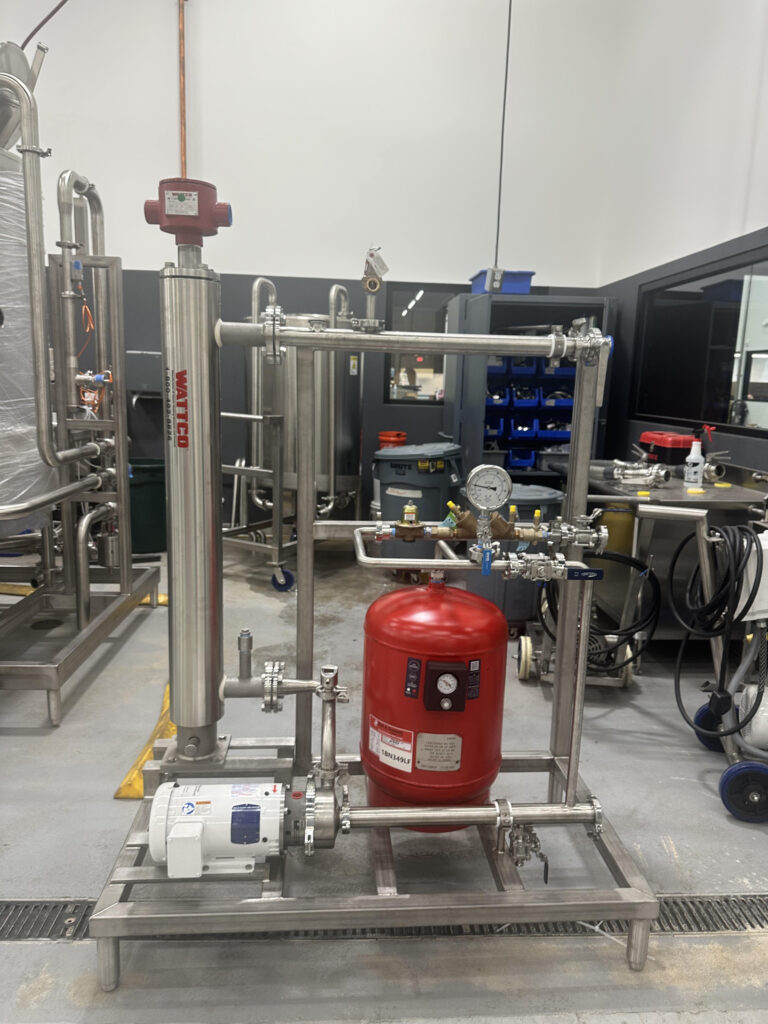
Our PureLine D PH systems are aimed specifically at providing UV treatment for product and process waters used in the food and beverage industry.
By using a UV system you will eliminate harmful micro-organisms, reduce the bio-burden, protect against bio-fouling, lead to fewer CIP/SIP cycles and lower operating costs. Each system comes with a UV sensor to measure the active output of the UV system and make it easy to monitor and log performance.
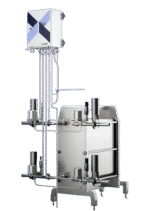
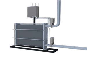
Potential Locations of the PureLine D PH™

Key Features
Intelligence
- UV intensity sensor measuring active wavelengths.
Optimization
- UV Water treatment.
- Designed for the food and beverage industry.
Integration
- Compact Design
Benefits For You
Intelligence
- Easy to monitor and log system performance.
Optimization
- Does not affect taste and color of final product
- No chemicals.
- Industry compliant materials.
- Sanitary Design.
- Self-Cleaning.
Integration
- Easy integration.
What It Gives You
Intelligence
- Continuous verification of performance with in-built low intensity alarm.
Optimization
- Protect your process waters from microbiological contamination including chlorine resistant Cryptosporidium and Giardia.
- FDA-approved materials used for all wetted parts.
- Chamber with tri-clamp connections and < 0.38 µm internal finish.
- *Automatic wiper (quartz cleaning).
Integration
- Can be fitted to skids.
- Can be retrofitted to existing process.
For more information, visit our website: www.mgnewell.com and www.newellautomation.com.


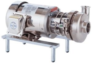
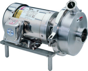
 Pump rebuilds can be performed by M.G. Newell in any of our 3 locations – Greensboro, Louisville or Nashville. As a SPX Certified Repair Center, M.G. Newell has qualified factory service technicians on staff with over 30 years of experience. We have invested in equipment, inventory and training to become one of a select group of distributors that are approved.


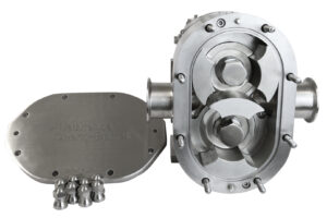
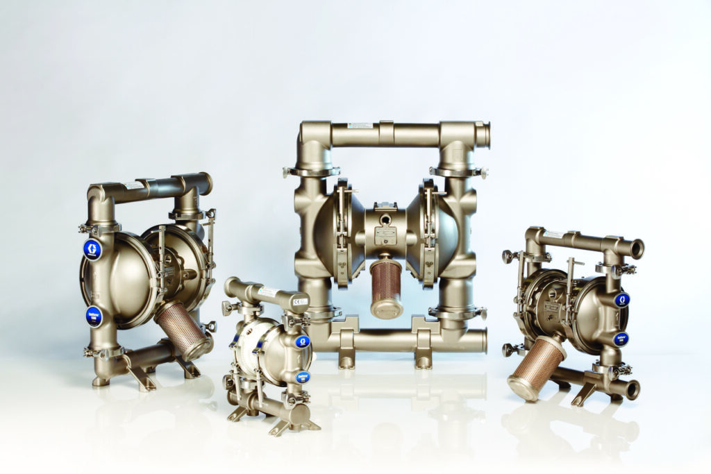
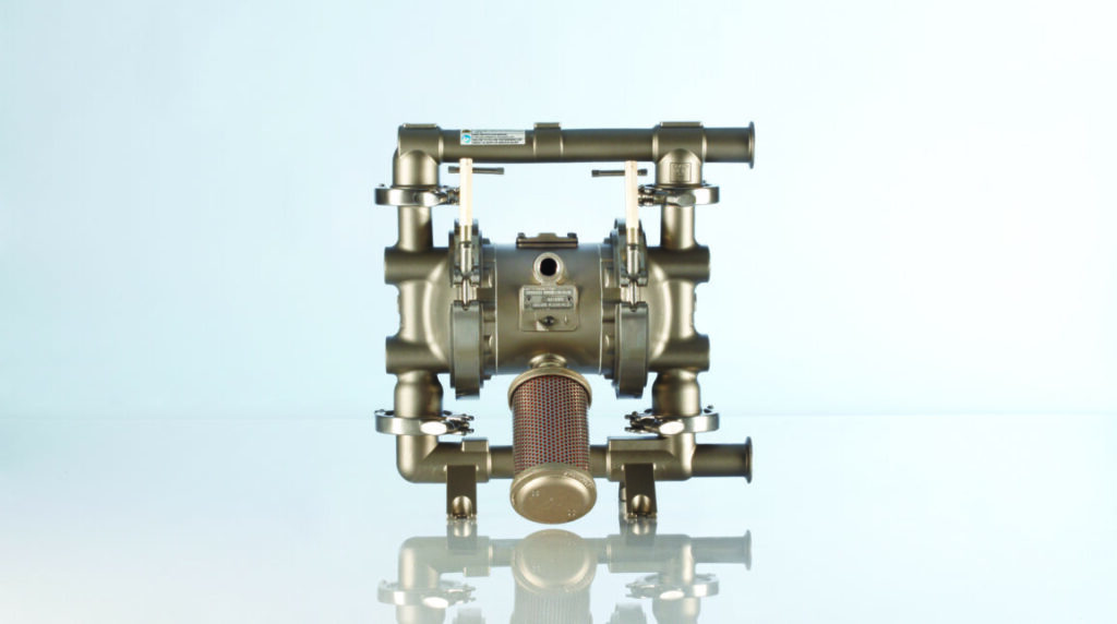
 Air Chambers: The pump has two chambers, one on the left side and the other on the right side of it. These